Continue to Site

Welcome to our site!

Electro Tech is an online community (with over 170,000 members) who enjoy talking about and building electronic circuits, projects and gadgets. To participate you need to register. Registration is free. Click here to register now.

  • Welcome to our site! Electro Tech is an online community (with over 170,000 members) who enjoy talking about and building electronic circuits, projects and gadgets. To participate you need to register. Registration is free. Click here to register now.

A basic electronic interlock circuit

Status
Not open for further replies.

CTR

New Member
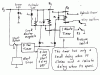
I'm looking for some kind of circuit that will alert a user that there is Hydraulic power being supplied around a system and prevent the opening of any guarding to a machine. Once the Hydaulic power has been stopped a safety time-out will only allow access after 1 minute.

Can anyone help me on this please, it would be very much appreciated if you could :wink:

Thanks in advance.


Liam
 
I will probably not have the best solution as I do not think you need a uC for that. However, do you have voltage driving something you want to tap, or a pressure switch in the lines if possible. We will need the voltage if that is the case.

So is this to be a circuit that taps the power, beep and flashes when power is there, after power is gone, delay 1 minutes and turn off all the noise and lights?

The machine commercial? Where people can look at it for more details.. More details will help. And also, liablity issues here.

Also, what are the inputs on the guard machines?
 
Basically what I need is:

LED to indicate overall system power

LED to indicate Hydraulic pressure/flow is present (therefore electronically locking the mechanical door interlocks)

Once Hydraulic power has been terminated, timer starts and after 1 minute releases the locks on the guard interlocks allowing access to the machine.

Hydraulic power cannot start backup until all interlocks are closed.

On restarting Hydraulic power, switch has to be held for 5 seconds (at the same time sounding an alert siren to alert the potential danger) before the Hydraulic system powers back up.


My situation is this - I am a Modern Apprentice who has been given a project by my boss in conjunction with my college to come up with this. I am mainly mechanical but do have an ONC in Electronics so I have a basic understanding. I am a bit out of my depth on this one though but really want to put the effort in on this to produce the goods and pass my HNC. If someone is able to produce/point me in the direction of something like this I would be eternally grateful.

The circuit doesn't have to have massive detail and an LED placed in the circuit to indicate that the Hydraulic pump is pumping oil around the system will more than suffice in this situation.
 
This circuit does not have to be uilt, only simulated. All I need to prove is functionality not practicality.

All circuit states ie interlocks locked/unlocked can therefore be represented by different colour LED's etc.

Please can someone help me. I'm desperate for help on this :(
 
if this is an industrial product (not a hobby, people are paid to work with or around the machine) you better check out applicable machine safeguarding standards. in north america it's Z432-04. you mention hydraulic. if this can qualify as press, you also need to check Z142-02 which is additional and more strict standard.
 
Here is the basic idea for you.

When power is applied, L1 glows. When S is pressed, the siren sounds, R1 operates after 5 sec, the Lock electromagnets are energised and L2 glows.

R1 operates R2 which holds to the Stop Switch via its lower contact. R1 & R2 apply power to the hydraulic system. When the hydraulic pressure has built up, PS closes and provides a hold path for R1 via the 1 minute timer.

S can now be released.

When the stop switch is pressed, R2 releases and when the pressure drops, PS goes open, starts the 1 min timer.

After 1 min, R1 is released and the electromagnets are de-energised.

Edit. I accidentally drew D1 & D2 the wrong way around. They should point downwards.
 

Attachments

  • hydraulic.gif
    hydraulic.gif
    87.2 KB · Views: 1,110
I thought this was to monitor an existing industrial machine (from the first post). I guess he was looking for a controller to run and monitor the machine.

I would use a uC for it. Block diagram the microcontroller (inputs and outputs) and flow chart the software.

Tie it into ljcox's diagram..
 
Russlk said:
Very nice, Bill. I am sure you realize by now that LED2 should be connected to pin 2 of the relay!

We've all been there :lol:

It's actually a bad choice of location, a better place would have been between the other LED and the diode across the relay - where it would have automatically been easy to connect properly.

I suspect that LED was added afterwards, which is why it went wrong?.
 
Status
Not open for further replies.

Latest threads

New Articles From Microcontroller Tips

Back
Top