AcousticBruce
Member
I have relooked at all your pictures, its puzzling?
I assume the probes are set to divide by 10.
Disconnect the scope and use your DMM to measure the ac into the bridge and the fullwave rectified voltage on the output of the bridge.??
Lets know.?
They are 10x probes your right. As for it being puzzling... did you mean you are puzzled or you couldnt understand why I am puzzled? I was puzzled because it still seems like a half wave rectifier with the scope.
I did some tests with a 220µf 16v cap. and a 12V 250mA Fan
With no cap or fan
AC=11.34V
DC=9.76V
With Fan only
AC=10.97V
DC=8.58V
With Fan and Capacitor
AC=10.84V
DC=11.62V
Maybe this might help. This is all new to me. I am having a blast in the process though
")
 why you dont see the full wave, only half wave.
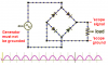

")
