AcousticBruce
Member
I posted 2 pictures just to make it easy.
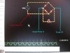
The wall wart says Input 120VAC output 9VAC.
why is my multimeter saying 11.29VAC?
Also why, even on new 9V batteries is it always around 7.5V?
**broken link removed**
**broken link removed**
The wall wart says Input 120VAC output 9VAC.
why is my multimeter saying 11.29VAC?
Also why, even on new 9V batteries is it always around 7.5V?
**broken link removed**
**broken link removed**
Last edited:
")