Continue to Site

Welcome to our site!

Electro Tech is an online community (with over 170,000 members) who enjoy talking about and building electronic circuits, projects and gadgets. To participate you need to register. Registration is free. Click here to register now.

  • Welcome to our site! Electro Tech is an online community (with over 170,000 members) who enjoy talking about and building electronic circuits, projects and gadgets. To participate you need to register. Registration is free. Click here to register now.

8x8 matrix proto' notes

Status
Not open for further replies.

Mike - K8LH

Well-Known Member
Hi guys,

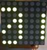
I'm finally getting around to building a matrix Signboard/Clock (after receiving a bunch of 2.2 inch 8x8 matrix display samples a couple years ago).

This prototype is just an experiment to test the new (to me) Micrel MIC5891 serial-to-parallel 500 ma sourcing driver IC and my PWM display driver.

I'm using 2N7000 row drivers with VBB and VDD connected to 5 volts. The current limiting resistors are not used (shorted out) because of the rather high Rds(on) resistance of the 2N7000's.

The Signboard/Clock will include six or seven 8x8 modules and I will use Si2312BDS MOSFETs which are rated for 4 to 5 amps with Rds(on) of 0.03 ohms.

Regards, Mike
 

Attachments

  • 8x8 display.PNG
    8x8 display.PNG
    1.1 MB · Views: 769
  • 8x8 board.PNG
    8x8 board.PNG
    753.3 KB · Views: 670
  • K8LH 8x8 prototype.PNG
    0 bytes · Views: 487
  • 8x8 Experiment (BoostC).c.txt
    0 bytes · Views: 193
Last edited:
Hi guys,

I'm trying to figure out what source voltage to use to light my 8x48 Signboard/Clock to full brightness with a 1/8th or 12.5% duty cycle.

The GMC2488C LED matrix has a VF rating of 2.1 to 2.8 volts at 20 ma. Each output on the MIC5891 sourcing driver IC will drop approx. 1.9 volts at VCE(SAT). The 5 amp N-FET sinking row drivers will only drop approx. 30 to 150 millivolts, depending on how many of the 48 LEDs are lighted in a row.

Now if 20 ma "average" current per LED produces full brightness at 100% duty cycle then I would need approx. 160 ma "peak" current for a 12.5% duty cycle, right? Does that imply that I need a VF of 16.8 to 22.4 volts across each LED? Somehow that doesn't seem right...

Mike
 
Last edited:
Mike,

Did you checkout the constant current drivers TI is making.

TPICxx
- 8-channel, adjustable output current from 5mA to 120mA
- Diagnostics: open-Load, short-load, over-temperature detection

TLC5940
- Dot-Correction adjusts for brightness variations between LEDs
- 16-channels and grayscale PWM control

3v0
 
Now if 20 ma "average" current per LED produces full brightness at 100% duty cycle then I would need approx. 160 ma "peak" current for a 12.5% duty cycle, right? Does that imply that I need a VF of 16.8 to 22.4 volts across each LED? Somehow that doesn't seem right...

Mike

LEDs are like zener diodes in that they will always drop the same voltage no matter how much current you put through them. In reality, there is a slight increase in the voltage across the LED with increase in current but it is minimal and can normally be ignored.

Mike.
BTW, before anyone points out the fact, I know zeners do it backward.:D
 
Mike,

Did you checkout the constant current drivers TI is making.

TPICxx
- 8-channel, adjustable output current from 5mA to 120mA
- Diagnostics: open-Load, short-load, over-temperature detection

TLC5940
- Dot-Correction adjusts for brightness variations between LEDs
- 16-channels and grayscale PWM control

3v0

Hi 3v0,

I looked at the TI constant current drivers briefly and the Allegro constant current drivers too. Nice features. I have samples of the Allegro parts that I'd like to try soon.

Mike
 
LEDs are like zener diodes in that they will always drop the same voltage no matter how much current you put through them. In reality, there is a slight increase in the voltage across the LED with increase in current but it is minimal and can normally be ignored.

Mike.
BTW, before anyone points out the fact, I know zeners do it backward.:D

Hi Mike (Pommie),

Thank you for that info'. Does that mean I might be able to use a 5 volt source then? 5 volts minus the 1.9 volt drop on each MIC5891 output minus approximately 100 millivolts across the N-FET row driver? Then fit a current limiting resistor that drops 0.2 volts at 160 ma to put 2.8 volts across each LED? Would that be something like a 1.25 ohm value for each current limiting resistor?

Mike
 
Last edited:
According to the datasheet for the GMC2488C, absolute max' peak forward current is 100mA at 1/10 duty cycle.
Hi geko,

Yes, I saw that "peak" current spec' in the GMC2488C Data Sheet. Do you know if that spec' can be exceeded?

I'm looking at the power supply requirements now and I'm thinking that I might want to limit the LED "average" current to about 15 ma and LED "peak" current to about 120 ma. This would allow me to install a simple 5v/1a smps buck regulator on each 8x8 module circuit board since the maximum power requirements for each 8x8 module would be 8 * 120 ma = 960 ma (with all 8 LEDs in a row lighted at the same time).

What do you think?

Mike
 
Hi Mike (Pommie),

Thank you for that info'. Does that mean I might be able to use a 5 volt source then? 5 volts minus the 1.9 volt drop on each MIC5891 output minus approximately 100 millivolts across the N-FET row driver? Then fit a current limiting resistor that drops 0.2 volts at 160 ma to put 2.8 volts across each LED? Would that be something like a 1.25 ohm resistor?

Mike

You would need to check the Vf of the LEDs as that may be slightly higher at 160mA. The datasheet should have a graph. But, yes, you could use 5V but I doubt you would need the 1.25Ω resistors.

Mike.
 
Thanks for all the feedback guys. I think I'm getting closer to building my next 8x8 module prototype.

Originally I thought I would install eight N-FET row drivers on each 8x8 module (six modules total for an 8x48 matrix). But now that I have these 5 amp N-FETs with a remarkable 0.03 ohm RDS(ON) spec' (at VGS = 4.5v) I'm thinking I might just use eight of them, each one driving a 48 LED row. This provides a little more room on each 8x8 module circuit board for a 5v/1a smps buck regulator circuit if I decide to do it that way.

So now each 8x8 module might look like the sketch below (2nd sketch). The eight N-FET drivers will reside on the MCU board with a 10 pin buss going to the display module chain. I need to invert my data when the buss is being used to load the MIC5891 shift registers during the display blanking interval but that should not be a problem. And I believe there's enough room on each circuit board to include a 5v/1a buck regulator if I decide to do it that way (lots of room under these huge 2.2 inch displays). The first drawing shows how I intend to connect the modules together.

So for 15 ma "average" current per LED my power supply needs to provide 5.76 amps continuous current when all 48 LEDs in each row are lighted with my PWM brightness level set to 100% brightness.

What do you think guys?

Mike
 
Last edited:
Status
Not open for further replies.

Latest threads

New Articles From Microcontroller Tips

Back
Top