Continue to Site

Welcome to our site!

Electro Tech is an online community (with over 170,000 members) who enjoy talking about and building electronic circuits, projects and gadgets. To participate you need to register. Registration is free. Click here to register now.

  • Welcome to our site! Electro Tech is an online community (with over 170,000 members) who enjoy talking about and building electronic circuits, projects and gadgets. To participate you need to register. Registration is free. Click here to register now.

8051 with real time clock

Status
Not open for further replies.

Parth86

Member
hello,
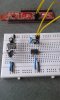
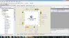
I am making design on proteus software. I am interfacing RTC with 8051 and LED
my task
turn on LED for 30 second
turn off lED for 1 minute
turn on LED for 30 second
turn off LED for 1 Hours
turn on LED for 30 second
turn off LED for 1 day
upload_2015-4-4_23-52-18.png


How to write c code for minute , day and also check circuit ?
can someone explain with small example
 
First! Do not use the "RES" model for the SDA and SCL pullups!! The I2C won't work properly... Use the "PULLUP" resistor primitive.... You'll find it in the library.... I have posted ALL the low level C routines... They are for the SDCC compiler so you will have to change the defines to suit your compiler..

You will need a BCD to Binary routine and one to swap back..

BCD to binary

Binary = BCD >> 4 * 10..
Binary += BCD & 0xF..

Binary to BCD

BCD = Binary / 10 << 4..
BCD += Binary % 10..

Or if you are just using the values and not displaying them then just use BCD....
 

Attachments

  • i2c.h
    1.7 KB · Views: 401
  • i2c_eprom.h
    1.2 KB · Views: 316
actually I made post #1 just for learning c program
actually I have cy8ckit -049-42xx Psoc 4 prototyping KIt (cortex m0). I only need c code. I did google search, I found all about LCD display. but I need code for LED. I am attaching two pictures

pin 1, 2 connected with crystal
pin 3 connected with 3.3 v battery
pin 4 connected with ground
p3.0 SCL connected with pin 5
p3.1 SDA connected with pin 6
pin 8 connected with vcc

My task
LED will turn on for 20 seconad
LED will turn off for 1 houre
LED will turn on for 10 minute
LED will turn off for 1 hours

here I just need to place c code
Code:
*/
#include <project.h>

int main()
{
    /* Place your initialization/startup code here (e.g. MyInst_Start()) */

    /* CyGlobalIntEnable; */ /* Uncomment this line to enable global interrupts. */
    for(;;)
    {
        /* Place your application code here. */
    }
}

/* [] END OF FILE */

how to write c program for minute , hours , day and months ?
 

Attachments

  • 20150404_155716.jpg
    20150404_155716.jpg
    580.4 KB · Views: 427
  • pin_diagram.jpg
    pin_diagram.jpg
    271.9 KB · Views: 421
I just create an array called TIME

unsigned char TIME[7];

Then I use the I2C to load the array every cycle. I created two functions to Write to the RTC and Read the RTC
C:
*/
#include <project.h>
#include "i2c.h"

unsigned char TIME[7];

void Readtime(unsigned char* array)
   {
    unsigned int idx, tmp;
   for(idx=0;idx<7;idx++)
      {
      tmp = RtcRead(idx );                   // read RTC
      array[idx] = tmp>>4 *10 + tmp;   // convert to decimal...
      }
   }
void main(void)  //<--- always a void in embedded systems
  {
    while(1)
      {
      Readtime(&TIME[0]);    // Reads the time... &TIME[0] is the address of the array
      }
  }

/*END OF FILE */

Once you have the array
TIME[0] = Seconds
TIME[1] = Minutes
TIME[2] = Hours
TIME[3] = Weekday
TIME[4] = Day
TIME[5] = Month
TIME[6] = Year
TIME[7] = Control

bit 7 of seconds is the on / off
bit 6/7 of the hours is the AM / PM

Control has the square ware output settings ( you can use this as the 1 second interrupt.)
 
The Ds1307 has the address of 0xD0... Everything on an I2C bus has an address... EEproms are usually 0xA0
hello ,

I saw following code. I am trying to understand.
Code:
sbit SCL=P3.5;
sbit SDA=P3.1;
void start();
void wirte(unsigned char);
delay(unsigned char);

void main()
{

start();
write(0xA2); //slave address//
write(0x00); //control register address//
write(0x00); //control register 1 value//
write(0x00); //control regiter2 vlaue//
write (0x28); //sec value//
write(0x50) ;//minute value//
write(0x02);//hours value//
}

void start()
{

SDA=1; //processing the data//
SCL=1; //clock is high//
delay(100);
SDA=0; //sent the data//
delay(100);
SCL=0; //clock signal is low//
}
void write(unsigned char d)
{

unsigned char k, j=0×80;
for(k=0;k<8;k++)
{
SDA=(d&j);
J=j>>1;
SCL=1;
delay(4);
SCL=0;
}
SDA=1;
SCL=1;
delay(2);
c=SDA;
delay(2);
SCL=0;
}
void delay(int p)
{
unsignedinta,b;
For(a=0;a<255;a++); //delay function//
For(b=0;b<p;b++);
}
 

Attachments

  • CyRTC_V_1.70_001-79201.pdf
    287.8 KB · Views: 373
hello Ian
please look at following code. there is time array. but I don't understand how does time array used in code
Code:
*/
#include <project.h>
#include <stdio.h>

#include "DS1307.h"

#define ADDR 0x68

#define SET_TIME 1


uint8 wrBuff[9] = {0x00, 0x00, 0x00, 0x00, 0x00, 0x00, 0x00, 0x00};

int main()
{
    uint32 rdStatus = 0;
    uint32 wrStatus = 0;
    uint32 nTime = 0;
    uint8 rdBuff[16];

    CyGlobalIntEnable; /* Uncomment this line to enable global interrupts. */
   
    LCD_Start();
    LCD_PrintString("Hello");
    I2CM_Start();
   
   
//    SetTimeArray(&wrBuff[1], 0x00104500, 0x02131209, (DS1307_ST_12HR|DS1307_ST_PM|DS1307_ST_SQOUT_1HZ) );
   
    SetTimeArray(&wrBuff[1], 0x00054000, 0x01131215, (DS1307_ST_12HR|DS1307_ST_PM|DS1307_ST_SQOUT_1HZ) );

    CyDelay(200);

    // Set time function, uncomment to set time.
//    wrStatus = I2CM_I2CMasterWriteBuf(ADDR, wrBuff, 9, I2CM_I2C_MODE_COMPLETE_XFER);
    CyDelay(20);
;
   
    for(;;)
    {
       
   
        I2CM_I2CMasterClearStatus();
        wrStatus = I2CM_I2CMasterWriteBuf(ADDR, wrBuff, 1, I2CM_I2C_MODE_COMPLETE_XFER);
        CyDelay(20);
        wrStatus = I2CM_I2CMasterStatus();

       
        I2CM_I2CMasterClearStatus();
        rdStatus = I2CM_I2CMasterReadBuf(ADDR, rdBuff, 8, I2CM_I2C_MODE_COMPLETE_XFER);
        CyDelay(20);
        rdStatus = I2CM_I2CMasterStatus();

        LCD_Position(0,0);
        LCD_PrintString(GetTimeString(rdBuff, (DS1307_TIMEDATE2|DS1307_AMPM)));
       
        LCD_Position(1,0);
        LCD_PrintString(GetTimeString(rdBuff, DS1307_MDY));
       
        nTime = GetSeconds(rdBuff);
        LCD_Position(1,9);
        LCD_PrintInt16((uint16)(nTime >> 8) );
        LCD_Position(1,13);
        LCD_PrintInt8((uint8)(nTime & 0x00FF));

        CyDelay(500);
        /* Place your application code here. */
    }
}


/* [] END OF FILE */
 
SetTimeArray(&wrBuff[1], 0x00054000, 0x01131215, (DS1307_ST_12HR|DS1307_ST_PM|DS1307_ST_SQOUT_1HZ) );
This function takes the whole array as a pointer &wrBuff[1] then the next two parameters contain BCD information to fill the array.. The final parameter is for the Square wave ouptut control and 24 /12pm parameters

The function is more like C++ style programming.. The two BCD longs look like the set time 00:05:40:00 /13/12/15
 
I just create an array called TIME

unsigned char TIME[7];

Then I use the I2C to load the array every cycle. I created two functions to Write to the RTC and Read the RTC


Once you have the array
TIME[0] = Seconds
TIME[1] = Minutes
TIME[2] = Hours
TIME[3] = Weekday
TIME[4] = Day
TIME[5] = Month
TIME[6] = Year
TIME[7] = Control

bit 7 of seconds is the on / off
bit 6/7 of the hours is the AM / PM

Control has the square ware output settings ( you can use this as the 1 second interrupt.)

as you said about time array I created time array

time array
RTC_WriteAlarmSecond(5u);
RTC_WriteAlarmMinute(3u);
RTC_WriteAlarmHour(1u);
RTC_WriteAlarmDayOfMonth(1u);

void I2C_Init(void);

// Set the minute as 55 (BCD format)

SetTime.Minutes = 0x55;
SetTime.Hours = 0x64;

I don't understand how to use array in program ?
 
You don't have to use an array... It just makes the job easier..

The first 8 registers of the DS1307 are the time registers.... I transfer all 8 registers in one read ( for speed ) I can then manipulate and display their contents..

I also like to work in decimal not BCD, so I convert the data to decimal for reading and then convert back to BCD to writing...

Look at these statements

C:
unsigned char PrinBuf[17];
unsigned char TIME[7];
while(1)
    {
    ReadTime(&TIME[0]);         // also does BCD conversion

    sprintf(PrintBuf,"%02d:%02d %02d/%02d/20%02d", TIME[2],TIME[1],TIME[4],TIME[5],TIME[6]);
    LcdOut(PrintBuf);
    }

This makes keeping track effortless
I am not using LCD .
I am repeating again , what I want to do with ds1307 using LED

Operation

Set alarm for 5 second (automatically turn on LED for 5 second )
Set alarm for 3 minute (automatically turn on LED for 3 minute)
Set alarm for 1 hours (automatically turn on Led for 1 hours )

SCL connected with P3.5;
SDA connected with P3.1;
LED connected with P1.6

LED will read the data form ds1307 via i2c pins

Code:
#include <project.h>
#include "i2c.h"
sbit SCL=P3.5;
sbit SDA=P3.1;
sbit LED=P1.6
void main()
{

RTC_ReadTime()
RTC_ReadTime(0x00)   //  address value of seconds  register
RTC_ReadTime(0x01)   //  address value of mintues  register
RTC_ReadTime(0x02)   //  address value of hours  register address


RTC_WriteTime()         // set alarm for specific time
RTC_WriteAlarmSecond(5u); // set alarm for 5 second
RTC_WriteAlarmMinute(3u);  // set alarm for 3 minute
RTC_WriteAlarmHour(1u);    // set alaram for 1 hours


RTC_WriteAlarmSecond()  // set alaram for second
{
SDA=1; //processing the data//
SCL=1; //clock is high//
delay(5);
SDA=0; //sent the data//
SCL=0; //clock signal is low//
}

RTC_WriteAlarmMinute()

{
SDA=1; //processing the data//
SCL=1; //clock is high//
delay(3);
SDA=0; //sent the data//
SCL=0; //clock signal is low//
}


RTC_WriteAlarmHour()

{
SDA=1; //processing the data//
SCL=1; //clock is high//
delay(1);
SDA=0; //sent the data//

SCL=0; //clock signal is low//
}


}
[/QUOTE]
 
Your code is not correct... The write to the I2C bus is a specific sequence..

If you want to write to the device you have to:

setup a start condition ( if bus is ready )
write device address ( wait for ack )
write register address ( wait for ack )
write device data ( wait for ack )
send nack ( to stop device )
send stop ( to free bus )


If you want to read from the device you have to:

setup a start condition ( if bus is ready )
write device address ( wait for ack )
write register address ( wait for ack )
send re-start( wait for ack )
read device ( send ack if more data needed )
send nack ( to stop device )
send stop ( to free bus )

Without this the device won't respond....
 
Status
Not open for further replies.

Latest threads

New Articles From Microcontroller Tips

Back
Top