Continue to Site

Welcome to our site!

Electro Tech is an online community (with over 170,000 members) who enjoy talking about and building electronic circuits, projects and gadgets. To participate you need to register. Registration is free. Click here to register now.

  • Welcome to our site! Electro Tech is an online community (with over 170,000 members) who enjoy talking about and building electronic circuits, projects and gadgets. To participate you need to register. Registration is free. Click here to register now.

8 bits binary number to 3 digit display

Status
Not open for further replies.

Cable

Member
Hello:

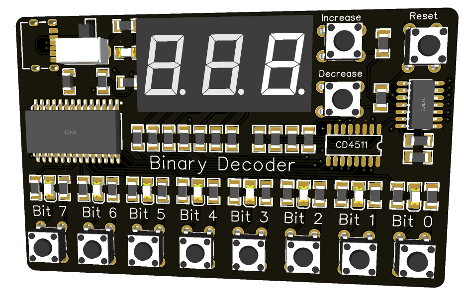
I am working with a digital circuit which includes counters and registers and I need to display the outputs of four 8 bits registers. Because I have not been involved with soldering for many years, instead of spending time on constructing four such devices with three 7 segment display per each, I wonder if there is any commercial device which accepts 8 bits data as input and displays the BCD as 3 decimal numbers.

My google search finds devices that accept asynchronous input to display decimals. But I need a device that takes 8 bits binary number as input to display it as 3-digit decimal number.

Could anyone tell me if such device exists as ready to use or at least as a kit?

Thank you
 
Last edited:
1. 8 bits BCD would display as only two digits, 00 through 99.

OR

2. Are you talking about taking a single 8-bit binary byte, decoding that to a decimal range of 0 through 255, and displaying that - ?

If <2>, then no. There is no chip that does what you want. IIRC there used to be some rarely used TTL or CMOS parts that decoded 4-bit binary to two-digit BCD, 0 through 15. If so, that was long ago.

I like CPLD's, and a small one could do this easily. Most people would use a PIC or AVR with 18 I/O pins, programmed to take in the byte, decode it to BCD, convert the digits to 7-segment coding, and multiplex them out on 10 pins.

ak
 
Last edited:
At some parts in my question I was supposed to write "binary number" instead of "BCD". But I did write in my question "any commercial device which accepts 8 bits data as input and displays the BCD as 3 decimal numbers."

So does anybody know about a device that takes an 8 bits binary number as input to display it as 3 digit decimal number?
 
There are these..
 
1. 8 bits BCD would display as only two digits, 00 through 99.

OR

2. Are you talking about taking a single 8-bit binary byte, decoding that to a decimal range of 0 through 255, and displaying that - ?

If <2>, then no. There is no chip that does what you want. IIRC there used to be some rarely used TTL or CMOS parts that decoded 4-bit binary to two-digit BCD, 0 through 15. If so, that was long ago.

I like CPLD's, and a small one could do this easily. Most people would use a PIC or AVR with 18 I/O pins, programmed to take in the byte, decode it to BCD, convert the digits to 7-segment coding, and multiplex them out on 10 pins.

ak

thank you.
I am not sure what you meant by AVR but PIC would be great. Do you happen to have any schematic of a simple PIC that could just do the display of the 8 bits binary number?
 
There are these..
Thank you for your reply. The bord looks great except that it has so much more than what I need. I was hoping for a board like that where it would simply take the 8 bits binary to display it.
 
There is no simple combinational logic to go from 8-bit binary to BCD.

One way to convert binary to BCD without using a micro, is to use a binary down-counter coupled to a BCD up-counter.
The binary counter counts down to zero from the binary input value, while the BCD counter counts up from zero at the same time.
When the binary count reaches 0, the BCD counter contains the binary value in BCD.
This is further discussed here.
To display the 255 maximum of the 8-bits would require two 4-bit binary down counters and three BCD up counters.
To go directly to the BCD display, you could use a BCD counter with 7-segment output such as the CD4026.
 
Last edited:
There is no simple combinational logic to go from 8-bit binary to BCD.

One way to convert binary to BCD without using a micro, is to use a binary down-counter coupled to a BCD up-counter.
The binary counter counts down to zero from the binary input value, while the BCD counter counts up from zero at the same time.
When the binary count reaches 0, the BCD counter contains the binary value in BCD.
This is further discussed here.
To display the 255 maximum of the 8-bits would require two 4-bit binary down counters and three BCD up counters.
To go directly to the BCD display, you could use a BCD counter with 7-segment output such as the CD4026.
Thank you for your help. Displaying 8 bits is a more difficult task than I thought. I also found ICs such as 4511 and 4543 which take 4 bits as input to drive a 7 segment display. These ICs have a built in latch but I want to display the outputs of a latch that is already in my circuit. Do you think it is right to use the 4511 which has its own built in latch or there might be simpler ICs that can receive the input binary number and just decode it to drive the display?
 
I also found ICs such as 4511 and 4543 which take 4 bits as input to drive a 7 segment display.
They will only display BCD outputs, not the 8 bit binary you want to display. You also asked about a pic to do the job, are you aware that the pic will need programming?

Mike.
 
Yes I am aware about the need for programming the PIC. I think that will be the next thing to think about. I just have to provide the display and I cannot spend too much time on it.
 
Are you able to program a pic? Do you know asm or C. You will need (at least) 18 I/O pins. eight for input, seven for the segments and 3 for the digits. There are some 20 pin pics available but I currently can't find them.

Mike.
 
You could actually use a ROM (eg. an EPROM or Flash memory) plus a bit of logic, as a look-up table system to translate binary to decimal, and include the 7 segment decode.

eg. Use four locations for each binary value, with a counter connected to A0 and A1 then the binary input to A2 - A9. The ROM data outputs would form the segment drives and decodes from the counter form the anode or cathode power switches for the multiplex.

But, an MCU such as a PIC doing that internally and driving the display should be simpler and cheaper, hardware-wise, if you don't mind doing a bit of software.
That also gives you the choice of display type, anything from individual 7 segment characters, serial loaded multi digit, a single LCD or OLED panel, dot matrix or colour Neopixel matrix etc.
 
One approach, single chip, most resources unused, could be used for other parts of design.

1634592997363.png


This is codeless, uses simple Verilog I lifted from another web page.

The input counter drives the input to the Verilog converter, that in turn outputs
3 separate BCD digits. The input counter for test purposes only, eliminate and
connect input byte directly to pins. If I was more diligent I would have modified
the Verilog code to mux the digits out to save HW. Just lazy.

Codeless design if you do not use any of the other chip capabilities.

Based on https://verilogcodes.blogspot.com/2015/10/verilog-code-for-8-bit-binary-to-bcd.html

Note in chip schematic above I did not hook up the other two digits, was in a hurry, but you
get the idea.


Regards, Dana.
 
Last edited:
Thank you all of you for trying to help me with my question. I will take some time to find my way based on all your suggestions.
 
I did a Verilog solution that used most of chip resources, in the BCD to 7 seg
portion, so think thats not viable.

A simple solution is in ROM store a 256 entry table, eg. 256 x 3, and use a pointer
to access the table with the binary value to retrieve each digit.

Here is a text listing that you can possibly edit into C array form and paste into your code.
Note you only need columns 2 - 4, column 1 just used by me to create the excel table.
Col2 = MSD
Col3 = Middle SD
Col4 = LSD

Then after retrieving digit use a 7 segment lookup table to translate into segment data for LED display.

0,0,0,0

1,0,0,1

2,0,0,2

3,0,0,3

4,0,0,4

5,0,0,5

6,0,0,6

7,0,0,7

8,0,0,8

9,0,0,9

10,0,1,0

11,0,1,1

12,0,1,2

13,0,1,3

14,0,1,4

15,0,1,5

16,0,1,6

17,0,1,7

18,0,1,8

19,0,1,9

20,0,2,0

21,0,2,1

22,0,2,2

23,0,2,3

24,0,2,4

25,0,2,5

26,0,2,6

27,0,2,7

28,0,2,8

29,0,2,9

30,0,3,0

31,0,3,1

32,0,3,2

33,0,3,3

34,0,3,4

35,0,3,5

36,0,3,6

37,0,3,7

38,0,3,8

39,0,3,9

40,0,4,0

41,0,4,1

42,0,4,2

43,0,4,3

44,0,4,4

45,0,4,5

46,0,4,6

47,0,4,7

48,0,4,8

49,0,4,9

50,0,5,0

51,0,5,1

52,0,5,2

53,0,5,3

54,0,5,4

55,0,5,5

56,0,5,6

57,0,5,7

58,0,5,8

59,0,5,9

60,0,6,0

61,0,6,1

62,0,6,2

63,0,6,3

64,0,6,4

65,0,6,5

66,0,6,6

67,0,6,7

68,0,6,8

69,0,6,9

70,0,7,0

71,0,7,1

72,0,7,2

73,0,7,3

74,0,7,4

75,0,7,5

76,0,7,6

77,0,7,7

78,0,7,8

79,0,7,9

80,0,8,0

81,0,8,1

82,0,8,2

83,0,8,3

84,0,8,4

85,0,8,5

86,0,8,6

87,0,8,7

88,0,8,8

89,0,8,9

90,0,9,0

91,0,9,1

92,0,9,2

93,0,9,3

94,0,9,4

95,0,9,5

96,0,9,6

97,0,9,7

98,0,9,8

99,0,9,9

100,1,0,0

101,1,0,1

102,1,0,2

103,1,0,3

104,1,0,4

105,1,0,5

106,1,0,6

107,1,0,7

108,1,0,8

109,1,0,9

110,1,1,0

111,1,1,1

112,1,1,2

113,1,1,3

114,1,1,4

115,1,1,5

116,1,1,6

117,1,1,7

118,1,1,8

119,1,1,9

120,1,2,0

121,1,2,1

122,1,2,2

123,1,2,3

124,1,2,4

125,1,2,5

126,1,2,6

127,1,2,7

128,1,2,8

129,1,2,9

130,1,3,0

131,1,3,1

132,1,3,2

133,1,3,3

134,1,3,4

135,1,3,5

136,1,3,6

137,1,3,7

138,1,3,8

139,1,3,9

140,1,4,0

141,1,4,1

142,1,4,2

143,1,4,3

144,1,4,4

145,1,4,5

146,1,4,6

147,1,4,7

148,1,4,8

149,1,4,9

150,1,5,0

151,1,5,1

152,1,5,2

153,1,5,3

154,1,5,4

155,1,5,5

156,1,5,6

157,1,5,7

158,1,5,8

159,1,5,9

160,1,6,0

161,1,6,1

162,1,6,2

163,1,6,3

164,1,6,4

165,1,6,5

166,1,6,6

167,1,6,7

168,1,6,8

169,1,6,9

170,1,7,0

171,1,7,1

172,1,7,2

173,1,7,3

174,1,7,4

175,1,7,5

176,1,7,6

177,1,7,7

178,1,7,8

179,1,7,9

180,1,8,0

181,1,8,1

182,1,8,2

183,1,8,3

184,1,8,4

185,1,8,5

186,1,8,6

187,1,8,7

188,1,8,8

189,1,8,9

190,1,9,0

191,1,9,1

192,1,9,2

193,1,9,3

194,1,9,4

195,1,9,5

196,1,9,6

197,1,9,7

198,1,9,8

199,1,9,9

200,2,0,0

201,2,0,1

202,2,0,2

203,2,0,3

204,2,0,4

205,2,0,5

206,2,0,6

207,2,0,7

208,2,0,8

209,2,0,9

210,2,1,0

211,2,1,1

212,2,1,2

213,2,1,3

214,2,1,4

215,2,1,5

216,2,1,6

217,2,1,7

218,2,1,8

219,2,1,9

220,2,2,0

221,2,2,1

222,2,2,2

223,2,2,3

224,2,2,4

225,2,2,5

226,2,2,6

227,2,2,7

228,2,2,8

229,2,2,9

230,2,3,0

231,2,3,1

232,2,3,2

233,2,3,3

234,2,3,4

235,2,3,5

236,2,3,6

237,2,3,7

238,2,3,8

239,2,3,9

240,2,4,0

241,2,4,1

242,2,4,2

243,2,4,3

244,2,4,4

245,2,4,5

246,2,4,6

247,2,4,7

248,2,4,8

249,2,4,9

250,2,5,0

251,2,5,1

252,2,5,2

253,2,5,3

254,2,5,4

255,2,5,5


Regards, Dana.
 
I'm still on Team LUT (look-up-table). Back in the day, an 8K EPROM (1K addresses x 8 bits per address) comes very close to a "single-chip" solution. The outputs would represent three multiplexed BCD digits, so you would need an oscillator and 2-bit counter to drive the upper two address bit inputs, a BCD-to-7-segment decoder driver on the output, plus three digit driver transistors. Each output byte has 4 bits with the BCD value for a digit, plus one-of-three bits active to drive the correct display digit.

These days, a PIC would be smaller and cheaper (and available), but still the look-up table approach would be the a whole lot easier than writing and debugging the seven Boolean equations for a calculated solution.

ak
 
Something I learned long ago, never used, and forgot. If you assign one byte to every element in the scratch space, then the 8-bit example given would need 48 bytes for the scratch space. Much less than a 255-element LUT, but also much slower. The LUT is not only faster, but also has a lower, and constant, latency. Still, I can see a real advantage for larger input numbers, such as 16 bits.

ak
 
Used an example of Verilog implementation of Double Dabble off web seems to be simulating right.

Single chip, Verilog based.

module BintoBCD8bit (
output reg [3:0] BCD1,
output reg [3:0] BCD2,
output reg [3:0] BCD3,
input [7:0] bin
);

//`#start body` -- edit after this line, do not edit this line

//Internal variables
reg [11:0] bcdt;
reg [3:0] i;


//Always block - implement the Double Dabble algorithm

always @(bin)
begin
bcdt = 0; //initialize bcd to zero.
for (i = 0; i < 8; i = i+1) //run for 8 iterations
begin
bcdt = {bcdt[10:0],bin[7-i]}; //concatenation

//if a hex digit of 'bcd' is more than 4, add 3 to it.
if(i < 7 && bcdt[3:0] > 4)
bcdt[3:0] = bcdt[3:0] + 3;
if(i < 7 && bcdt[7:4] > 4)
bcdt[7:4] = bcdt[7:4] + 3;
if(i < 7 && bcdt[11:8] > 4)
bcdt[11:8] = bcdt[11:8] + 3;
end
BCD1 <= bcdt[3:0];
BCD2 <= bcdt[7:4];
BCD3 <= bcdt[11:8];

end

//`#end` -- edit above this line, do not edit this line
endmodule


Modified the Verilog code so each digit output and then followed it with a mux into 7 segment Verilog decoder,
seems to be working pretty good on a PSOC. Problem is the 7 seg decoder takes a lot of resources. Tried it with
a standard LUT, and then with Verilog code, same result. PSOC fabric just not suitable for that. Makes a fine stand
alone solution, but shame the other 85% of the PSOC resources, digital, not available. Still lots of analog stuff can
be used onchip however.

1634859593969.png


Regards, Dana.
 
Last edited:
Status
Not open for further replies.

Latest threads

New Articles From Microcontroller Tips

Back
Top