Continue to Site

Welcome to our site!

Electro Tech is an online community (with over 170,000 members) who enjoy talking about and building electronic circuits, projects and gadgets. To participate you need to register. Registration is free. Click here to register now.

  • Welcome to our site! Electro Tech is an online community (with over 170,000 members) who enjoy talking about and building electronic circuits, projects and gadgets. To participate you need to register. Registration is free. Click here to register now.

7805 regulator, Vout>Vin?

Status
Not open for further replies.

Blueteeth

Well-Known Member
Hi all,

Despite the topic title, I'm not trying to use a simple linear regulator to 'step up' voltage :)

Essentially I have several 'modules' I've made for various microcontroller stuff, and because I wanted to use them 'standalone' on each one I have included a simple 7805 reg circuit, with a DC socket for a plug-in power supply.

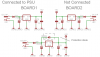
This works like a charm, but.... would it be possible to use just one of these regulators, and power the other boards from it? (we're talking <100mA total system current). The reason I ask is because then all the regulators on each of the other boards would then have their outputs at 5v, but their inputs at 0v. Would a simple diode going from Vout to Vin be sufficient? Essentially we are tlaking about having parallel regulators, with their Vout's tied, BUT only one regulator's Vin has voltage.

I haven't implemented 'jumpers' for on board power supplys, or diodes in series with the regulators outputs, so unless the diode thing works, I will have to build a power supply with multiple DC jack cables, one for each board >.<

Sorry for the simple question, hope someone can help, I 'would' test this, but I really don't want to blow any of the regulators, because they are not easy to replace on these PCB's (Dpak, SMT).

Cheers,

Blueteeth
 
Diodes in series with the outputs of the regulators would disconnect them from being fed voltage in reverse which is good. But then the output voltage of the one that is being used will be only 4.3V unless its diode is jumpered.
 
Yep, thats why I didn't do it in the first place. Even a diode on the GND of the regulator to boost its output to 5.6v (ish) wouldn't really compensate for the diode drop on the output, since the GNd current is smaller than the regulator current. But would a diode from Vout to Vin be sufficient? as that can easily be 'added' to the boards I have...got loads of SMD shottky power diodes.

I might sacrifice a few stock 7805's for a test. If they blow, then they blow.
 
Try it.
I have never fed voltage backwards to a regulator. Maybe they will survive with a Schottky diode across them.
 
@Blueteeth
not sure what your problem actually is .. as, Vin on the 7805 will not be grounded ?! or I missed something out... the 5V coming to the Vout will not (tried more then once, but you can try yourself) will not damage the 7805 if the Vin is NC. I tried this only with "normal trough hole" 7805's but I do not see reason why would smd ones be any different...
 
@Blueteeth
not sure what your problem actually is .. as, Vin on the 7805 will not be grounded ?! or I missed something out...

You missed something out :D I'll attach a quick schem of what I mean...

And I mentioned 'SMD's, but I have to modify several of my boards. Desoldering the head off a DPAK regulator can be tricky, as the copper pad itself IS a heatsink, and so draws a lot of heat from the solder connection.

Blueteeth
 

Attachments

  • dualreg.png
    dualreg.png
    10.2 KB · Views: 298
I feel stupid but still do not get it .. look at my schematic .. I'm using this all the time .. only one of the 7805 get's V on the imput, all other 7805 have imputs just NC and everything works ok .. I do not see how is your schematic different then this one ?!
 

Attachments

  • wth.gif
    wth.gif
    15.3 KB · Views: 344
Just to be 100% accurate, the inputs will be floating, not at 0V, correct? That makes a difference...

Also, there are some SPST one position DIP switches on Digikey that fit in the same holes that a standard diode would (0.3" pitch).
 
@speakerguy79 that's what I'm trying to determine, as If input is grounded, then I can see possible problems with 7805 dying .. but if they are left floating .. I see no reason for it not to work .. (using that setup attm ... and if there is a reason why that is not good, I would like to know about it)

looking at the 7805 internal schematic (attached) I do not see how 5V on the output and floating input can make it "die" ...

I still prefer jumper on the output (as I do for all my new boards) so I can actually disable the whole power section as I noted that 7805 draw some small amount of current when attached to the circuit .. small but, easy to add jumper to the new boards .. old ones still work like a charm ..
 

Attachments

  • 7805.gif
    7805.gif
    23 KB · Views: 362
Isn't this the same as having a big capacitor on the 5V rail and switching of the power? This situation is very common and doesn't cause any problems.

Mike.
 
Right yes, the input to the 'other regualtors' on the other boards are indeed floating. Only one will have power going into the reg on its board....the other boards will be powered by this board via a 10 pin header (8 I/O's, power, GND). I jsut wanted to check with you guys that this was 'ok' and not awful design practice.

Arhi, yep, exactly like your schematic. All outputs of the regulators will be effectively 'tied' together. They all share the same ground. but only one has input voltage.

Well sounds like its 'ok' for now. I'll let anyone know if I happen to blow something :D And arhi, thanks, I will indeed place a jumper on my boards in future if they have power on other output pins (which could then be used to power the board, without the on board reg). Its always good to get a 'standard regulator circuit' in ones library so you can just copy/paste it to any quick design. Cheers guy!.

Blueteeth
 
Status
Not open for further replies.

Latest threads

New Articles From Microcontroller Tips

Back
Top