MrDEB
Well-Known Member
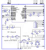
Using the attached schematic, I adjust the tempctr pot (5k) and the LCD display dims.
I measured the voltage on the 7805 output as well as other points but read mv not 5 as it should.
What is wrong with my power supply design? the 7805 bad or ?
sorry for the negative power supply image
wondering if the two 300 ohm resistors are to big? not enought current but the circuit works ? it just goes dim while adjusting either the tempctr pot or the sensor value resistor (the pic is set up to read ADC and compare the two. I added more resistance to the voltage dividers in the ADC section. seemed to help a little until I added the opti-coupler to the mix.
I get the feeling I amd drawing too much current but the 7805 is not getting warm. MAYBE BAD?
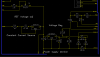
") The LM317 can handle a much higher input (~38-40 V) so will easily handle the ~ 32V DC out of the bridge rectifier/ smoothing cap
The LM317 can handle a much higher input (~38-40 V) so will easily handle the ~ 32V DC out of the bridge rectifier/ smoothing cap