Continue to Site

Welcome to our site!

Electro Tech is an online community (with over 170,000 members) who enjoy talking about and building electronic circuits, projects and gadgets. To participate you need to register. Registration is free. Click here to register now.

  • Welcome to our site! Electro Tech is an online community (with over 170,000 members) who enjoy talking about and building electronic circuits, projects and gadgets. To participate you need to register. Registration is free. Click here to register now.

74HC595 Long Distance Triggering

Status
Not open for further replies.
what exactly you need to do? (what is the baud rate, environment,...?)

when dealing with long runs, you either need to:
a) lower impedance of the line and
b) limit the data rate

or

you need to use something that works around this (such as line drivers, that's why they are invented).

low impedance helps dampen noise, this is why analog phone lines do not need coaxial cables (voice takes little bandwidth but many people use it also for DSL).
this is also why cable TV is using low impedance trunk.

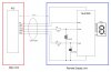
line drivers are used as buffers that convert I/O signal into a symmetrical pair of signals which is run over twisted pair (say MAX485 or similar).
on the other end signal is converted back to 'normal'. this allows you to run high speed signals with little if any sensitivity to noise over longer distances. such circuits need to be terminated (low value resistor, usually 80-120 Ohm, depending on exact network type)
 
Simply I need to show a number on the segment display.So I just send 8 bits & make a latch pulse thats it.No UART involved.

Every 1 second I send this packet.

To make a low impedance line what modifications do I have to use...!!!
 

Attachments

  • 595 long distance.JPG
    595 long distance.JPG
    66.5 KB · Views: 256
Last edited:
Simply I need to show a number on the segment display.So I just send 8 bits & make a latch pulse thats it.No UART involved.

Every 1 second I send this packet.

To make a low impedance line what modifications do I have to use...!!!


Suraj143, did you solved the problem, with this schematic ?.


I trying do to a similar schematic, using some transistor 2N3094 and 2N3096 to replicate the signal to RJ-45 cable, in this way, protecting the PIC.
 
Suraj143, did you solved the problem, with this schematic ?.


I trying do to a similar schematic, using some transistor 2N3094 and 2N3096 to replicate the signal to RJ-45 cable, in this way, protecting the PIC.

Hi it worked nicely on workbench & never tested on industrial situation.

Be sure to add some delay when triggering clock & latch signal on 74HC595.
 
Ok, thanks for the tip.

I'm getting good results with the transistors BC557 and BD137. Here is my test circuit:

2013-06-07_00-27-58_3831.jpg

RC Filter (1k2 resistor and 220pf capacitor):

a2013-06-07_00-29-21_7491.jpg

Wave compare (Blue = After the BD137 on sender board, Yellow= At the third and last receiver board):
a2013-06-07_00-30-52_164.jpg


Aprox. 10 - 15 meters of RJ-45 cable.


Att;
Daniel
 
Last edited:
Hi are you using the same 74HC595 for receivers end?

For PIC transmitting side you using transistors instead of direct PIC pin?
 
Hi are you using the same 74HC595 for receivers end?

Each receiver board has a 74hc595.

For PIC transmitting side you using transistors instead of direct PIC pin?

Yes, that is right. But in this test, i put the BC557 and BD137 only in the Register Clock pin. Other pins are direct connected on PIC.

I will post the schematic (i don't have yet) to clarify the ideia.
 
Ok thanks but you don't need transistors to that "Serial Clock" pins as well.A series 100R resister will be fine on all pins.
 
Status
Not open for further replies.

Latest threads

New Articles From Microcontroller Tips

Back
Top