Electro Tech is an online community (with over 170,000 members) who enjoy talking about and building electronic circuits, projects and gadgets. To participate you need to register. Registration is free. Click here to register now.
Welcome to our site! Electro Tech is an online community (with over 170,000 members) who enjoy talking about and building electronic circuits, projects and gadgets. To participate you need to register. Registration is free. Click here to register now.
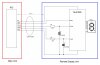
Depending upon the signal frequency that should work. But if you use the same ground for the input and output of the opto isolators as you show, then you have no isolation and don't need the isolators.
If you really need isolation, then the output of the isolators must use the power and ground from the 74HC595 power, not the drive circuit power.
Actually I don't need isolation,just for false triggering & low voltage inputs I used opto couplers.
The controlling voltage is 5V logic signals directly coming from PIC pins over 30 meters distance.
The frequency is very low.I just to show a single digit number on a seven segment display.After sending data to the shift register it will latches the signal.
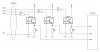
You could put around a 2k2 resistor to ground on the '595 input to reduce noise sensitivity, also diodes from the input to both supply rails connected reversed would protect the chip from inductive swings you might get on the long lines.
I cant remember the numbers but I think holtek do a couple of chips designed to transmit data over 2 core cable, there are parallel input/output bits at both ends, seen one in a slot car.
You can also get a lot of noise immunity by using an RC filter and some Schmidt trigger buffers at the receive end.
As for using the optocouplers, unless you need galvanic isolation or level shifting, they probably make the noise problem worse. Ideally, you want to drive the line with as low an impedance as practical. That way any induced noise gets shunted back to the source. I would recommend a 100 ohm resistor on each line, but otherwise run them direct to the remote display.
And if you want to reduce the number of wires between your controller and the display, you might look at this idea. https://www.romanblack.com/shift1.htm
Hi Chris thanks for mentioning my project there. That project drives the 74HC595 with ramping voltages, which works fine as the 595 has well defined LO and HI trigger levels on it's pins (works like schmidt trigger inputs).
The simplest way would be to do like you said, just send RC filtered logic levels that have a slowish changing signal, and the 595 inputs at the receiving end should do the rest.
Only the CLK and LATCH signals need an RC filter, the DAT line edge noise will not affect anything, because you activate CLK after DAT has become stable.
I like to go for RC filtering but the problem is then it needs protection diodes to protect the 595 side due to long distance inductive kick back that means too much components on the receiving side.
...
I like to go for RC filtering but the problem is then it needs protection diodes to protect the 595 side due to long distance inductive kick back that means too much components on the receiving side.
...
Not really. If you RC filter before sending, the signals have slowly ramping voltages on the / and \ edges, and you will get zero inductive effects caused by the line. A distance of 30 feet is nothing much!
Or if you RC filter at the receiving end, any high speed edge transients etc won't get through the filter.
Wouldn't 30m of wire act like a "long wire" antenna?
Have you considered using a pair of RS485 drivers or transceivers instead? They're designed to be relatively noise immune over long distances. Then use a PIC, like 3V0 suggested, to decode an incoming serial byte and drive the display.
You don't need a 33k resistor! If you make both resistors 1k or 1k5 that will be fine.
Just allow enough "settling time" between setting the DAT line and making the CLK pulse, and enough time again before makign the LAT pulse.
How are you getting a 5 core cable?
8 core cables are quite common too, and did you realise with an 8 core cable you can run 7 segments and ground, and just drive the display digit directly with no other ICs needed?
I always put about 100 ohms in series with all digital lines that I let go on or off a board. That usually provides enough current limiting so that the on chip protection diodes can handle the energy from any transients.
I always put about 100 ohms in series with all digital lines that I let go on or off a board. That usually provides enough current limiting so that the on chip protection diodes can handle the energy from any transients.
That's a nice point, ok I'll use resisters on PIC side board even 1K will be ok. But onchip clamp diodes will active when the PIC pin is in input mode.So that means after sending data do I need to make PIC ports as inputs?
This site uses cookies to help personalise content, tailor your experience and to keep you logged in if you register.
By continuing to use this site, you are consenting to our use of cookies.

 that means too much components on the receiving side.