Continue to Site

Welcome to our site!

Electro Tech is an online community (with over 170,000 members) who enjoy talking about and building electronic circuits, projects and gadgets. To participate you need to register. Registration is free. Click here to register now.

  • Welcome to our site! Electro Tech is an online community (with over 170,000 members) who enjoy talking about and building electronic circuits, projects and gadgets. To participate you need to register. Registration is free. Click here to register now.

7447 Circuit

Status
Not open for further replies.

sala

New Member
Hi,
I am building a circuit which includes a 7447 BCD Decoder.
It worked before, I was able to see the display change numbers, but all of sudden, I guess by changing other things, I lost it!!!
I have been working for a while trying to figure it out, but no success.
Anyway, I disconnected all my wires, including my 2 display 7 segment LED, and resistors, except Pins 1 (Vcc), 8 (Gd), 3 (LT) and my 4 Binary Inputs, and using an LED light, I have been testing my outputs at "a" through "g".
I noticed that my LED turns on at my Inputs, but I am not getting any LED On at any of my outputs "a>g".
Is this a feasible test? My goal is to troubleshoot why my 7 segment is no longer displaying anything.
I am sending in inputs, but not seeing outputs.
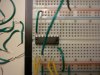
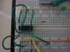
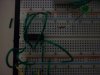
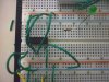
The circuit is below. By the way, pins 4,5 are not connected to anything.
Please help.
Thanks
Sala
 

Attachments

  • P1000137.JPG
    P1000137.JPG
    3.7 MB · Views: 599
hi,
I see that you have 1 & 2 linked also 6 & 7 , this means the inputs are HIGH, so as its TTL , the decoded output is BLANK.

connect these 4 pins to 0V to get "0" displayed.
 

Attachments

  • AAesp02.gif
    AAesp02.gif
    58.8 KB · Views: 463
Last edited:
Eric,
My inputs come from a timer, so they are blinking at all times, so are all my LED input checks.
My outputs are not blinking at all.
That's the question, and I am sorry that I forgot to mention that.
Thanks
Sala.
 
Eric,
My inputs come from a timer, so they are blinking at all times, so are all my LED input checks.
My outputs are not blinking at all.
That's the question, and I am sorry that I forgot to mention that.
Thanks
Sala.

hi Sala,
To check the 7447's are OK, I would connect pins 1,2 & 7 to 0V and leave pin 6 not connected.

This should give a number "8" on the 7segment LED connected to the 7447, thats ALL segments should be lit.
Connect pin 3, 4 & 5 to +5V.

The 7447 has open collector outputs, so if you dont have an LED connect via a limiting resistor you cannot measure a voltage on the output pins.

To check if its working you can use a 470R resistor and a single normal LED, connected between +5V and the output pins you want to test. With the input pins connected as I have just described, ALL the 7447 output pins should light the single LED.

I assume you are using a current limiting resistor in the 'a to g' outputs to the common anode 7 segment LED.???
 
Last edited:
Eric,
i think that my connections are wrong or something. i am using a SN74LS47, but your suggestions don't seem to work.
The breadboard is fine. I have tried up to 3 different chips, but something is going on inside these chips that is not translating to the output I need to see. The LED is still not lit!!
Please help.
The diagram is below.
 

Attachments

  • P1000138.JPG
    P1000138.JPG
    3.6 MB · Views: 390
Sorry,
This is the actual schematic of what you suggested, and the LED is not ON at all
 

Attachments

  • P1000139.JPG
    P1000139.JPG
    3.7 MB · Views: 266
Sorry,
This is the actual schematic of what you suggested, and the LED is not ON at all

hi Sala,
On some of those project boards the top and bottom rows have a 'gap' in the socket connections and a link is required.

Is this a new project board.????

Connect your power lines to the same end of the project board as the 74LS47,,, OK.??


EDIT:
Look at this
 

Attachments

  • AAesp05..gif
    AAesp05..gif
    44.6 KB · Views: 284
Last edited:
Eric,
A link is not required. I verified that.
Something else is going on.
I got this to work on Friday, but yesterday, I lost it.
I am not sure what happened.
hum..
 
Eric,
A link is not required. I verified that.
Something else is going on.
I got this to work on Friday, but yesterday, I lost it.
I am not sure what happened.
hum..

OK, we did have that problem with an OP last week, link missing.

Does that single LED work if you connect the resistor to 0V on that board.? so that the LED and resistor are in series from +5V to 0V.???

Check and let me know
 
Eric,
If I connect one end of the resistor to 0V then to one end of the LED, and the opposite end of the LED to 5V, yes the LED gets lit.

Sala.
 
What about pins 3 ( LT), 4 ( BI/ RBO) and 5 ( RBI)? Are they connected?
If pin 3 is low, all outputs are low ( on). You should get the LED lit when fed from the power row.
If pin 4 is low, all outputs are high ( off). The LED should be dark.
If pin 5 is high and ABCD = 0000, you should get a blank display ( no LED lit).
This should also be true for the 7448 IC, which uses pull-up resistors to VCC on its outputs.

hi,
Looking at his image shows that 3,4,5 are connected high,, A,B,C low and D floating pull up, so that decimal "8".

I suspect either the 7447 is faulty or he has a bread board problem.
 

Attachments

  • P1000139.jpg
    P1000139.jpg
    2.1 MB · Views: 260
Last edited:
Status
Not open for further replies.

Latest threads

New Articles From Microcontroller Tips

Back
Top