Continue to Site

Welcome to our site!

Electro Tech is an online community (with over 170,000 members) who enjoy talking about and building electronic circuits, projects and gadgets. To participate you need to register. Registration is free. Click here to register now.

  • Welcome to our site! Electro Tech is an online community (with over 170,000 members) who enjoy talking about and building electronic circuits, projects and gadgets. To participate you need to register. Registration is free. Click here to register now.

741 - Comparator problems

Status
Not open for further replies.

Nutmegzzzz

New Member
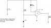
I have a 741 comparator circuit (attached) using a 6.2V zener diode as a reference voltage at IN- (Pin 2). I supply the IN+ (Pin 3) with a LiPO battery voltage of 7.2V (varies between 6.0 - 8.4 dependant on charge) and as the voltage falls I want the output to go from high to low when battery voltage is at ~6.0V. I see the 741 output a high well enough (Vcc = 6.4V; Output = 5.49V), but my problem is when the 741 outputs a low (Vcc = 6.3V; Output = 1.65V). It should be mentioned I am using the LiPO batteries to power the 741 Vcc + (Pin 7) and ground for Vcc- (Pin 4). I've tried putting a potentiometer at the offset but that really screws things up.

Note that I require the output to be zero so that I can interupt current flow with an opto-isolator and shut the system down to prevent the LiPO batteries from futher discharging and getting damaged.

The additional diode (D1 at the + input) is used to ensure the voltage at the + input will eventually become less then the - input. The 402 ohm resistor is used to limit current through the zener diode.

Thank you for your time and any assitance is very appreciated.

Bill
 

Attachments

  • 741 - Comparator.JPG
    741 - Comparator.JPG
    15.5 KB · Views: 927
The 741 is an inferior opamp that is not capable of reaching Vcc or ground at its output. You can solve this by using a different op amp, such as types advertised for "rail to rail output" for example, or any op amp that is rated to swing within 0.3 volts of V-. Otherwise, you live with a low output of 1.5 volts and add an additional transistor stage to translate this to ground. Or you could change the way you attach the optoisolator to tolerate a low of 1.5 rather than 0 volts.

The ability of an opamp to swing to V- is clearly stated in their data sheets. For example, the National data sheet for the LM741 calls the parameter "output voltage swing". The value given is +/-14 volts typical if the load is 10Kohms or greater. This tells us that if the 741 power supply is +/- 15 V, the output can reach -14 volts at the low side with light loading and about -13 volts under heavier loading. This difference between -15 and, say, -13 exists no matter what voltage you bias V- to. So if V- is set to 0 volts, then the output can only swing down to 2 or perhaps 1 volt. In your case, you got to 1.5 volts. Quite predicable using the data sheet info.
 
Last edited:
The inputs of an old 741 opamp don't work when their voltage is within 2V of the positive or negative supply. You have the input within 0.6V from the positive supply.

An old 741 opamp works poorly or not at all when its supply voltage is less than 9V. It is spec'd at 30V.

Use an LM10 which is an adjustable voltage reference and an opamp in an 8 pins package. Its output goes very close to ground.
Its minimum supply voltage is 1.1V.
Configure its voltage reference at 3.0V with 2 resistors and use 2 more resistors to make a voltage divider for its input. Connect it as a comparator with a voltage reference. One more resistor will add hysteresis so its output snaps quickly.
 
You need a comparator that draws nothing when your battery's output is below your designated voltage. Otherwise, the comparator will continue to discharge the battery even after it has disconnected the load.
 
Status
Not open for further replies.

Latest threads

New Articles From Microcontroller Tips

Back
Top