Continue to Site

Welcome to our site!

Electro Tech is an online community (with over 170,000 members) who enjoy talking about and building electronic circuits, projects and gadgets. To participate you need to register. Registration is free. Click here to register now.

  • Welcome to our site! Electro Tech is an online community (with over 170,000 members) who enjoy talking about and building electronic circuits, projects and gadgets. To participate you need to register. Registration is free. Click here to register now.

7-Segment LED counter

Status
Not open for further replies.

kadunk

New Member
Hi there,

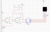
I am very interested in electronics and right now trying to understand some simple circuits so I was just wondering if someone can explain the 7-segment LED counter circuit and how it works. Can it be reversed so count from backwards and how can that be done?. And what is U2 used for?. What is Count In?

The site below is the circuit
https://www.aaroncake.net/circuits/counter.asp


Thanks in advance for any help
 
A pulse, for instance from a 555, is sent to U1 at "count in" (a square wave typically of 0V for low and 5V for high). U1 counts the pulses and provides a four-bit output. If U1 is configured for BCD (binary coded decimal) the U1 outputs will count from 0 to 9 (instead of 0 to F). U2 reads the four-bit output from U1 and decodes (translates) those values into the various configurations needed to display the 0 through 9 binary number as a 7-segment decimal number. U2 is designed for a common-anode 7-segment display, so it sinks the current passing through the display LEDs from the 5V supply. Sorry, I don't know off-hand how to make it count backwards.
 
Last edited:
hi,

> Can it be reversed so count from backwards and how can that be done?. And what is U2 used for?. What is Count In?

The circuit uses a 7490 decade counter, this counter can only count 'up' that is '0' thru '9' then back to '0' ,,, repeating

There are counters which can count 'up' and 'down', but they are not pin compatible with 7490. Examples, 74190, 74191..

U2 [7447] in the circuit decodes the 4 bit output from the 7490 counter in order to drive the LED segments.
The U2 [7447] ic would also work with a up/down counter input.

>> What is Count In?
Count in; is the source of the pulses you are counting, it could be a switch or a logic signal.


Does this help?
 
Last edited:
Thanks a lot guys I just bought a lot of electronic Books and started reading them hopefully before i go to college so i get a head start. Thanks a lot again
 
No problem, and (if I can speak for Eric) our pleasure. Keep coming back with your questions. It's good practice to ask, or try to answer, these types of things, and I invariably end up learning something useful from it.
 
Okay well another question =). I just found a program called multiSim 7. Now I was wondering how can i implement this in the program I have it designed but it doesn't work =( I really don't know what type of LED segment to use. if anyone can construct it and put it up here so I can see what you have done.


thanks
 
I would recommend a "common Cathode" 7-Segment. That way you just "sink" the current into the driver. The 7447's are designed for that, they output an active low signal.
 
Actually, the 7447 will require a common anode display. The 7448 is compatible with a common cathode device. Your image shows a common cathode display (note "CK" at it's top). "K" is often used to denote the cathode pin. Also, connect the -LT, -RBI and -BI/RBO inputs of your 7447 to +5v.
Jeff
 
Last edited:
Hi Kadunk,

LT and BI should be connected to +5V.
RBI/BO is an exception, it should be left open because it's
also an output, an open collector output. It should never
be connected directly to +5V.

on1aag.
 

Attachments

  • BI RBO 7447.GIF
    BI RBO 7447.GIF
    5.3 KB · Views: 1,384
Good point about -BI/-RBO being left open. It's been a long time since I used that chip.:rolleyes:
Jeff
 
hi,

Hi everyone,
I'm trying to make a simple BCD counter, from 0 to 3 only, using the 7447 and JK flip flops, i cant see where the error in the circuit is, as my 7 seg LED display doesn't light, can anyone help me here and check where is the problem in the circuit. I'll attach a pic of the circuit. Thanks

note: X1 and X2 are just probes
 

Attachments

  • New Picture (2).JPG
    New Picture (2).JPG
    172.5 KB · Views: 2,371
bashbash said:
Hi everyone,
my 7 seg LED display doesn't light, note: X1 and X2 are just probes

Just taking a quick glance at your circuit you probably have a blank display because you have all high imputs to the '47.

In TTL, untied pins usually show as high, and if both the A and B inputs are high, as I suspect they are, you will have four highs.
The truth table for the '47 shows a four-high input equals an all high output, which equals no segments lit.

If you are breadboarding, quickly tie the C and D inputs to ground and see what happens.
 
i'm using SN7447A and found 1.6v at the 4 inputs (A,B,C,D), even without any input signal. is that normal?
 
hmmm.....
i'm interfacing it's input to an MCU. but the MCU cant detect 1.6 as low. i tried pull it low, but when the dip is on (to 5v), the input still detect as grounded.

any way to make the input low (~0v) when dip switch is at off position, and high (~5v) when dip switch at on position?

thanks
 

Attachments

  • 7447 cct.GIF
    7447 cct.GIF
    46.5 KB · Views: 4,650
I saw on another thread someone saying the 7447 was inproperly coded on some sims, and gave false indications.

Perhaps that is your problem.
 
Status
Not open for further replies.

Latest threads

New Articles From Microcontroller Tips

Back
Top