Tom McCurdy
New Member
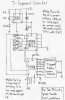
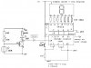
Here is something that I was able to build, it basically takes the pulse from a 555 timer and goes through a 7490 divide by 10 into a 7448 and finally into a LN514rk Common Cathode LED-- if you are going to use a common anode LED just replace the 7448 with a 7447
Materials Needed
Simply connect it as it is in the diagram
**broken link removed**
Materials Needed
- 5 V-Source
Wires
555-Integrated Circuit
7490-Integrated Circuit
7448-Integrated Circuit
7-Segment Display (the one I used was LN514RK)
Simply connect it as it is in the diagram
**broken link removed**