strokedmaro said:
Is there a way to get a seven segment to display numbers 1,2,3 and 4 with only 2 inputs?
Basically
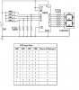
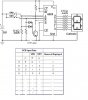
1=on,on
2=off,on
3=off,off
4=on,off
Yes, I think it is with suitable logic, but I don't think it is all that simple.
From your initial enquiry---
I presume you want to display 1,2,3,4
NOT 0,1,2,3
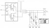
Nearly all logic devices (counters/ displays) are manufactured to count/display from 0- 3 ---> etc. So you will have to use an adder to increment a zero state (on,on) to (on,off) to satisfy a display module. A cmos 4008 will do that.
I also presume that you want to interpret the state of
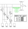
two lines, not a counter, hence you need a binary decoder. All I can see in the cmos is a 4555 that will give an A,B,C,D output.
I can not find a 7 segment display that will give 1,2 3,4 outputs with A,B,C,D inputs. EG 4511 will give A=1 B=2 BUT C=4 and D=8, So you will need to split the C and D outputs with Diodes to make discreet 4511 inputs C= (A+B inputs) and D = (
NOT A+B+ C inputs)
This is an interesting exercise and I will have a go at it myself.
There are probably many other ways to do all this, but I can only see this way.
Cheers
RH


") .....the solenoids have about 5 ohms of resistance and draw about 1 amp @12vdc. Could I attach a 5ohm, 5-10 watt resistor to the "auto" contacts of the switch to simulate the solenoids when in manual to prevent the computer from faulting an open circuit? Would the resistors have any impact on the solenoids operation while in auto? THANKS!!!
.....the solenoids have about 5 ohms of resistance and draw about 1 amp @12vdc. Could I attach a 5ohm, 5-10 watt resistor to the "auto" contacts of the switch to simulate the solenoids when in manual to prevent the computer from faulting an open circuit? Would the resistors have any impact on the solenoids operation while in auto? THANKS!!!