Continue to Site

Welcome to our site!

Electro Tech is an online community (with over 170,000 members) who enjoy talking about and building electronic circuits, projects and gadgets. To participate you need to register. Registration is free. Click here to register now.

  • Welcome to our site! Electro Tech is an online community (with over 170,000 members) who enjoy talking about and building electronic circuits, projects and gadgets. To participate you need to register. Registration is free. Click here to register now.

7 Segment Display - Switch Project - Help!

Status
Not open for further replies.

FLCARM1964

New Member
I am working on a project for a basic digital class.....HELP!!!!
Here is a description of the project:
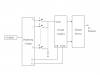
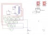
This circuit is to use ten switches to represent the ten pins used in bowling, with the switches (pins) arranged in the “bowling” triangle. The user closes a switch to indicate a fallen pin. As more switches are closed, a two-digit 7-segment display shows the number of fallen pins, from 00 to 10. For example, if switches (pins) 1, 3, 5, and 8 are closed, the display should read 04.

I am stumped.......Any guidance would be greatly appreciated.
I am using MultiSim to design the project with.
Thanks in advance!

CAF
_________________
Carmine
 
Carmine,
It won't help you if I do it for you, so I'll give you a hint.

I would connect one side of all of the switches together and connect this side to the input of a Decade Counter.

The other side of the switches would be connected to the decoded outputs of a Modulo 12 counter so that it applies a pulse to each of the switches in turn. The Decade Counter will only increment if the respective switch is closed.

If you design a circuit and post it in this forum, we can comment on any short comings.

Len
 
Carmine,
Your other respondent suggested using a PIC. This would be a good solution, but I assume the object of the exercise is to do a hardware design.

Len
 
ljcox said:
Carmine,
It won't help you if I do it for you, so I'll give you a hint.

I would connect one side of all of the switches together and connect this side to the input of a Decade Counter.

The other side of the switches would be connected to the decoded outputs of a Modulo 12 counter so that it applies a pulse to each of the switches in turn. The Decade Counter will only increment if the respective switch is closed.

If you design a circuit and post it in this forum, we can comment on any short comings.

Len

Len,
Thank for the guidance....I am at work now but will give it a try when I get home. The connecting the Other side of the switches to the outputs of a Modulo 12 Counter...I will try it....I am a bit confused though.The Decade Counter = Modulo 12?? I can't wait to try it.
Thank you
Carmine
 
Carmine,
You're welcome. You were on line a couple of minutes ago but I had not logged in.

The point of the Modulo 12 counter is to address the switches one at a time and also to do the sequencing - store the count and then reset the Decade Counter.

When you have thought about it, post your ideas so I and others can comment.

Len
 
Carmine,
Here is an outline. There are a few details to fill in.

Len
 

Attachments

  • pin_counter.png
    pin_counter.png
    1.6 KB · Views: 1,422
Bowling Pin Counter-------Issues still

Len and the rest of you Electronic Gurus....I am still having difficulty trying to figure out how to complete the circuit. Len I appreciate the help...but am still somewhat confused as how to complete the hookup. Attached is the pic of where I am right now.....I did have a Decade counter installed......no luck...perhaps my circuit is not correctly hooked up. Thanks to all in advance

Carmine
 

Attachments

  • bowling_pin_counter.doc
    267 KB · Views: 263
  • bowling_pin_counter.jpg
    bowling_pin_counter.jpg
    66.4 KB · Views: 891
  • bowling_pin_counter.jpg
    bowling_pin_counter.jpg
    66.4 KB · Views: 1,265
Carmine,
You must connect the A, B, C & D inputs to the 74HC154 to the respective outputs of the binary counter.

I am in a libray and don't have access to drawing software, so I hope you can make sense of this.

Counter A----A 74HC154
B----B
C----C
D----D

Also, you will need diodes in series with the switches to prevent the output that in low being affected by any that are high via the switch common.

I'll look at the internet tomorrow to see how you are going.

Len
 
Carmine,
I've just noticed another issue with your posted circuit. R1 should be connected the Vcc, not the gnd as shown. The decoder has active low outputs so the "pull up" resistor must be connected to Vcc to pull the clock line high when all switches are open. You also need diodes in series with each switch pointing towards the 74154.

Incidentally, key 0 should be the first, not the last. Zero is the first digit of all numbering systems, not the tenth.

Len
 
Carmine,
I've just noticed another issue with your posted circuit. R1 should be connected to Vcc, not to gnd as shown. The decoder has active low outputs so the "pull up" resistor must be connected to Vcc to pull the output line high when all switches are open. You also need diodes in series with each switch pointing towards the 74154.

Incidentally, key 0 should be the first, not the last. Zero is the first digit of all numbering systems, not the tenth.

Len
 
Status
Not open for further replies.

Latest threads

New Articles From Microcontroller Tips

Back
Top