Continue to Site

Welcome to our site!

Electro Tech is an online community (with over 170,000 members) who enjoy talking about and building electronic circuits, projects and gadgets. To participate you need to register. Registration is free. Click here to register now.

  • Welcome to our site! Electro Tech is an online community (with over 170,000 members) who enjoy talking about and building electronic circuits, projects and gadgets. To participate you need to register. Registration is free. Click here to register now.

6v / 12v Switchable Voltage Regulator Positive Ground

Status
Not open for further replies.

PackardDon

New Member
First just let me say hello and thank you for allowing me to be a part of this forum. To clarify, I am not an electronics engineer and know only the basics of electronic components but not the details needed for this project. Please be gentle with me!

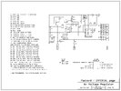
That said, I am working on a design for a voltage regulator for my vintage cars and I am hoping there is someone here with the skills to look over the schematic to see if it will work before I actually build it. A friend says it "makes sense" now after some errors the first few times but he was vague about whether it is something to be built or if more needs to be corrected.

This schematic is negative ground but is switchable from 6v to 12v and I will build it this way first but I also need it converted to positive ground or, better yet, switchable to positive ground. Can anyone help with any of these things? The design here should put out about 40A so is for larger charging systems than most I've found here and elsewhere.
 

Attachments

  • Regulator.jpeg
    Regulator.jpeg
    568.6 KB · Views: 289
Last edited:
The circuit diagram isn't at all easy to read. There are some useful comments about how to draw circuit diagrams here:- https://www.electro-tech-online.com/threads/rules-for-drawing-readable-schematics.144863/

The large schottky diodes that are used as a cut-out will generate quite a lot of heat and will need a big heat sink.

The AP34063 is used to switch on and off the field, so the basic idea is OK. The AP34063 switches the base current for T1, and the base current is limited to around 70 mA, so the maximum field current is about 3 A due to the gain of T1.

The layout of the 6V/12V switch isn't clear. It should be open for 6 V, which disconnects R9.

Also, the relay appears to just completely by-pass the regulator. When the generator runs, the relay will operate, and will connect the armature to the field, which will make the dynamo run at full output all the time.

It's not easy to get a dynamo regulator to work. You should read this thread:- https://www.electro-tech-online.com...r-universal-digital-voltage-regulator.159967/ I suspect that the design didn't control the dynamo correctly, and the relay was added to bypass the regulator. It would give the appearance of working, as the relay would turn off when the dynamo stopped working at tick over. However, with no regulator, the battery would be overcharged when driving on the highway with little electrical load. Of course, dynamos would always do that to some extent, and overcharging would take some time to be noticed, so the user might be fooled into thinking that they had a working regulator.

Making a circuit that is switchable for +ve or -ve ground is very complicated when working with 40 A. I would not recommend it.
 
Thank you for the great input. I drew it but did not design this circuit as I do not have the skills but rather it was reverse-engineered from a PC board layout of a commercial 40A regulator designed as a replacement for a vintage military vehicle. Unfortunately, the software does not have good control of font sizes so it was almost impossible to read when all the components had their values next to them, which is why the BOM. Also, I do not know the values of three of the capacitors so if there is some way to glean that from the design, I will add it to the BOM.

The large diodes do have a large heat sink so it is only the schematic that I need help with to make sure it all makes sense electronically. On the slide switch, it connects to nothing in 6v mode and, as you said, it adds the R9 resistor in 12v mode. The connector dot for the 6v mode somehow disappears whenever I convert the schematic to an image (a bug in the schematic software, apparently). I'm not sure what to say about the relay as it appears correct compared to the existing regulator from which it is based. The relay is NC between pins 1 and 4 and no connection when energized as pin 3 connects to nothing.

For switching ground, making it switchable was just a thought but I do need to make a version that is positive ground while retaining the 6v/12v switchability.

I had already read the page you linked before I posted but it seems to be based on a tiny and basic VW's two-relay regulator when those I am trying to replace have three relays.
 
Last edited:
This thread may be useful; "Danwww" has developed several functional 6V car regulators, though they are for VW and that uses a field switched to ground rather than power.

A slight rearrangement to invert the filed power control, such as a small N channel MOSFET replacing the power FET and that in turn controlling the gate of a P channel one, should get you something reasonable.

With slight changes around the voltage sensing and IC power supply, it could also work at 12V.
 
Although I looked through that page prior to posting, I'm afraid that I am not an electronics engineer as I stated at the top so all that is above my head. I would be happy, though, to hire someone who has the skills to make a design that will work for me. It needs to be switchable between 6v and 12v and handle 38A to 40A or be switchable between several amperages. I can be negative ground but I would also need a positive ground version for another application (I have vehicles of both types).
 
In my original post, I replaced the image with the switch being a little clearer and I added a pin-out inset for IC2. On the switch, the design software kept removing the 6v connection dot as there was no connection to it and that made the switch's housing grounds appear to be part of the connection when they were not. Whether or not this can be reduced in size to fit inside a Delco-Remy or Autolite housing and still keep everything cool enough it another matter that I'll cross when I get to that point.
 
For the relay doing nothing, here is how a friend described it:

IC1 is a regulator which is performing two jobs: operating the relay when a battery connection is present and to provide a stable supply voltage to IC2 which is the heart of this circuit.
 
I think Diver misread the relay contacts. It's normally closed, so the dynamo has the best conditions to self-excite.
Once it produces enough output to run the electronics the relay energises and opens the direct connection, so the electronics take over.

That's OK as a basic circuit, but has no current sensing or limiting.

If I were to design one, I'd use a small microcontroller so the operating characteristics could be changed without changing components.
6V / 12V is simple; positive or negative earth means different power circuitry.
 
Thank you so much for the clarification! As for a microprocessor, I would gladly try it if someone could help me with the design. Right now, reducing the design to fit into an automotive Delco-Remy and AutoLite housing has proven difficult and as it stands, all the power diodes at the right side in the schematic will have to be on a daughterboard standing vertically at the end of the main board. Similarly, either the large power transistor and its heat sink at the other end or all the little transistors, diodes and capacitors must be on another daughter board as otherwise nothing will fit.
 
Last edited:
Status
Not open for further replies.

Latest threads

New Articles From Microcontroller Tips

Back
Top