Continue to Site

Welcome to our site!

Electro Tech is an online community (with over 170,000 members) who enjoy talking about and building electronic circuits, projects and gadgets. To participate you need to register. Registration is free. Click here to register now.

  • Welcome to our site! Electro Tech is an online community (with over 170,000 members) who enjoy talking about and building electronic circuits, projects and gadgets. To participate you need to register. Registration is free. Click here to register now.

6S BMS question

Status
Not open for further replies.
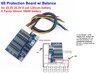
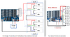
Hey, i am using the BMS 6S from the attachment (model of BMS if it helps is hx-6S-a06). I like this BMS. But there is 1 problem. The scheme how ur supposed to connect it is in the attachment. Till now i built several packs like this but today it got me thinking. Do you see that + and - are connected to their respective pins on board ? Well today i didnt connect any wires to B+ and B- and P+ and P- still gave me 25.2V. So i am thinking, is it possible that if u connect + of the pack to B+ and - of the pack to B-, that ur actualy ignoring the whole BMS and u do not get the protection ur supposed to ?
 

Attachments

  • s-l1600.jpg
    s-l1600.jpg
    288.8 KB · Views: 143
You have extra wires to what I found in Google:
 

Attachments

  • 6S BMS wiring.png
    6S BMS wiring.png
    439.5 KB · Views: 148
Thank you for finding this. But i am still not sure. It says B+ on the board and also B+ on the red wire coming out from the connector. If i understand the left picture, then the right picture simply connects to B+ 2 times, which is just fine ? My friend also said, it might be so that it can handle more current (2 connections).

Anyway, this is the downside of buying cheap chinese stuff. Even though i really really like this BMS. But anyway i decided to do a test. I would like to see if the low voltage protection kicks in in both of this cases:

1) when i connect exactly like it is connected on the right image that you attached

2) when i only connect the wires but do not connect to B+ and B- pin on board a second time.
 
Check if the two B+ and two B- are internally connected on the board, with a multimeter.

If they are, you probably do not need the extra two. If they are not, the balance circuit is probably disconnected without those wires.
 
Hmm, good call, cudos. I just measured and using multimeter between both B- will give me 0.1 Ohm. Same happens when connecting both B+.

So now it got me wondering even more, why add 2 connectors that are connected together. The only thing i can come up with is ... this board allows 8A current through it. Maybe they added this so there would be less resistance since ur spliting ur current through 2 wires instead of just 1. Though even if thats true, this will only help the flow from batteries to BMS. Internal bms components will still have only 1 way for current to flow.

I am still unsure whether to use 2 wires or 1 wire. My max current will be in the area of 2A. I will test tomorrow if there is any difference between both ways as far as low voltage protection goes. If i find that it works either way, i will just use 2 wire connection.
 
By connecting the extra wires you're increasing the accuracy of the measurement:
That's why I asked for the resistance reading, to see if it was intended as a four wire setup.

That would make definitely sense if they were not also directly connected at the PCB - but they are, according to a previous answer.
 
That's why I asked for the resistance reading, to see if it was intended as a four wire setup.

That would make definitely sense if they were not also directly connected at the PCB - but they are, according to a previous answer.

It still makes perfect sense, as you're removing the cables from the measurement, which is what four wire is all about.
 
Status
Not open for further replies.

Latest threads

Back
Top