Misterbenn
Active Member
Background:
A friend is looking to do some fractal burning (google it) (edit: also called Lichtenberg figure)
and has salvaged a microwave oven transformer (MOT) for this purpose. However he likes to think big and isn't satisfied with the 2kV output so has asked me to look at increasing it.
As a results I've done some research into transformer design and have a few questions that i'm hoping someone here can help with.
At this point i want to save you all the effort of pointing out how dangerous high voltages are (and i'm expecting a flurry of don't do this type comments). I'm aware of the risks of electrocution and the very small amount of current it takes to kill a person. I should mention that I've worked in HV (>20kV) test houses for many years and am fully aware of lab practices for safe testing of HV equipment.
Discussion:
I've no one specific question so this is more of a thought train written down and i'm interested if anyone has anything to add or corrections.
In my initial steps for designing the transformer I wanted to calculate the number of turns required on the primary. To do this i used the EMF equasion
E=4.44 f N_{P} B A
Inputting the mains frequency, voltage and the maximum flux density and area of a E core I have in my bits box:
E = 230 Vrms
f = 60 Hz
B = 1.5 T
A = 4.3 cm^2 = 0.00043 m^2
and re-arranging to get the minimum number of primary turns gives me 1338 turns.
This seems like a huge number of turns and wont fit on my core unless i reduce the wire size (and thus max power). But i know other mains transformers exist in smaller sizes, MOT for example. So how do they do this? the EMF equation seems very clear that you need a sizeable core if you don't want it to saturate at this voltage and frequency.
So it got me thinking ... how do they make a MOT so small without the core saturating.
Answer; An unloaded MOT will saturate and losses skyrocket, but in a microwave application the transformer secondary is always loaded and this reduces the flux density. So you must never use a MOT unloaded. see links **broken link removed**
http://www.qsl.net/kh6grt/page4/xfmr/xfmr.htm
I found this interesting but then thought "why don't wall wart transformers saturate". At the moment I can only think that they must have a large number of turns of small wire on the primary (>1500 turns). And that this is allowable due to the low power of the transformer.
The only example of a high power mains transformer that I can think of is a construction site transformer and these are fairly chunky and expensive.
So back to my friend and the Fractal Burning. If he wants to use a MOT or several in series he must make sure they are always loaded and also limit the arc current.
If we want to build our own transformer using the core that i have we will probably need to increase the frequency via an inverter to at least 1kHz.
If we are dead set on a mains transformer we need a much bigger core, or some way of calculating how much loading is required to keep it out of saturation.
As i said earlier I don't really have a question, this is just my thought process in my attempt to build a mains to several kV transformer. If anyone has any experience or knowledge they would like to share i'm interested
Another question do Lichtenberg figure need AC or can the same be acheived with DC?
Related threads / Links
- A thread already discussing fractal burning Wood art made with electricity.
- A thread discussing EHV power supply design Winding transformer for -40KV power supply.. Including a post by SPEC refering to MOT transformer flux saturation Winding transformer for -40KV power supply.
- A thread of cool arty photos of HV arcs Epic High Voltage Picture ( Got Lucky ).
Last edited:
 However, seeing as this is an open forum and this post may be viewed by others in the future: I recommend that anyone else who reads this post and wants to try it be safe and know the proper safety precautions for working around high voltages.
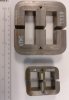
")
