Ok thanks...
Why i need that?
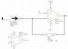
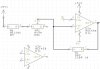
- If i don't power my opamp (LM324N) with Vcc=+5V and Vee=-5V my current and my voltage gives me a value that it's not supposed to be...
For example, if R1=1K and R2=150R using the inverting configuration Vcc=+5V and Vee=GND, i do not have Vout=(R2/R1)*Vin.
Can anybody tell what's happening?
Regards