Continue to Site

Welcome to our site!

Electro Tech is an online community (with over 170,000 members) who enjoy talking about and building electronic circuits, projects and gadgets. To participate you need to register. Registration is free. Click here to register now.

  • Welcome to our site! Electro Tech is an online community (with over 170,000 members) who enjoy talking about and building electronic circuits, projects and gadgets. To participate you need to register. Registration is free. Click here to register now.

5v = no led, 0v = 'LED'!!! : )

Status
Not open for further replies.

harps

Member
hello : )

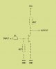
i wonder if you can help ? is there a simple circuit ( other than perhaps a relay) that when you send 5v into the circuit an LED is turned off and when the 5v is reduced to 0v the LED instead lights up : )

i have a fair few LEDs to turn off and on individually like this so am hoping to keep the current consumption as low as possible.

thanks for any help : )
 
What sort of output are you using to drive the LED?

Please post a schematic.

If it's a logic gate or 555 timer, there's no need to add anything, just connect the LED and resistor between 5V and the output.
 
Consider using a Flip Flop. A 7474 comes to mind but others would work. You don't mention how many LEDs or all at once or individual circuits?

Ron
 
Yes, you're right, I misread the post, you need a divide by 2 counter so a flip-flop will do. I'd recommend HC over TTL though.
 
An inverter is needed that can drive the LED. A common-emitter transistor or a logic inverter.

EDIT:
Connect the anode of the LED to +5V and the input signal through a current-limiting resistor to the cathode. when the input signal goes to 0V then the LED will light.
 
Last edited:
Just use a PNP transistor with the base grounded with a 10k resistor and a diode on the base attached to +V. I have one of these as a battery back up for my clock because the battery voltage is higher than the actual voltage supply for the clock.
 
Just use a PNP transistor with the base grounded with a 10k resistor and a diode on the base attached to +V. I have one of these as a battery back up for my clock because the battery voltage is higher than the actual voltage supply for the clock.

hi thanks for your replies

ive made a block diagram ( in the link below) of the type of circuit. Its a simple relay switched by an arduino. audio channel 1 or 2 is routed to the output of the relay. i am hoping for a red led to come on when ch1 is selected and a green led to come on when chn2 is selected.
**broken link removed**

i did buy a few PNP transistors, but i think i may have damaged them or wired them wrong?. i've managed to make an NPN transistor work that powers lots of relays from a single arduino output (so not to burn it out). but the PNP? i must have wired it wrong and burnt it out before i got it right. :? or i was missing a bit of info on how to wire it up.

thanks for your help : )
 
Last edited:
What's an arduino?

It sounds like you just need a DPDT relay, connect the channel selector to one set of contacts and the LEDs to the other set of contacts.
**broken link removed**
 
Hello : )

i managed to get this circuit to work below.... on my test table i used a 5.7volt psu as the input and a 10v psu as the VCC. all my leds are 5v type. Wow i forgot the 1k resistor to begin with on the input, the transistor became very hot when i applied power. owch. after i added the resistor it was fine.

Also changing the resistor value from the VCC to the collector i could up the volts/amps to turnoff/trigger a relay too. :)

i make sure the transistors and resistors are cool or warm to the touch when i make a change from now on. ( although a more advanced knowledge of electronics and multimeter usage would be more ideal perhaps, lol : P

i used a 2n2222 npn type transistor.

thanks for all your help :) top notch.


**broken link removed**
 

Attachments

  • npn not gate.jpg
    npn not gate.jpg
    7.9 KB · Views: 256
Last edited:
hi, hero its a type of microcontroller, i'm sure you know of other brands/models , but for those that dont know:

an arduino is a little external micro controller, you connect it up to your pc via usb , i use a program called Max msp to control it ( max msp is like a virtual bread board , but sooo much easier than electronics); and from this program i can trigger the Arduino to send out 5v or i can receive a signal too. (the little arduino has 12 digital in or outs and 6 analog ins or outs, from what i can see so far)

so it is a little in/out device ( costs about £27). one example i can trigger relays from my computer...or maxmsp can sense switches , its a way of conecting real world bread boards to the virtual bread boards.

you can also link up max msp to sequencers ( cusbase ,logic).

I found these real world bread board projects very complicated in comparison to the virtual stuff on maxmsp.

but to make something work on a real breadboard is much more rewarding. : )
 
I was thinking NOT Inverter, by far easier that most of the things people have been suggesting,
When input is high (5V) then output is low (0V) and the LED is off
When input is low (0V) then output is high (5V) and the LED is on

EDIT: Someone posted a Transistor NOT Schematic above
 
Last edited:
Status
Not open for further replies.

Latest threads

New Articles From Microcontroller Tips

Back
Top