Continue to Site

Welcome to our site!

Electro Tech is an online community (with over 170,000 members) who enjoy talking about and building electronic circuits, projects and gadgets. To participate you need to register. Registration is free. Click here to register now.

  • Welcome to our site! Electro Tech is an online community (with over 170,000 members) who enjoy talking about and building electronic circuits, projects and gadgets. To participate you need to register. Registration is free. Click here to register now.

556 Timer Toggle Flip Flop Circuit

Status
Not open for further replies.

umibuta

New Member
Hi all,

1st time posting and I am hoping I can get some help.

I am trying to build a LED light with a Piezo switch. I am using a single 3.7V Li-ION battery to drive this circuit. However, the toggle circuit (see attached) i can find seems to require a minimum of 6V. Is there a way to modify this circuit so that it runs on a 3.7V Li-ION battery? Or reuse the components for a new circuit.

I am illiterate when it comes to electronics if you could provide a drawing that would be best.

Thank you.

Cliff
 

Attachments

  • 7-Bill-Bowden-Inverter-circuit-revised.jpg
    7-Bill-Bowden-Inverter-circuit-revised.jpg
    22.4 KB · Views: 4,823
555/556s dont run well on voltages less than 5V. Try two CMOS 555s. They usually have a C in the part number, like C555. I dont remember seen a CMOS dual, so just use two chips.
 
Last edited:
Yep, Mike has pretty much covered this well :) As for part numbers, the CMOS versions are LM555, or TS555 NOT NE555. That said, I have got standard 555's running on 3v.

One possible thing: the schematic shows a MOSFET. Whilst these are great with their low on resistance...many require a relatively large gate voltage differential. That is to say...they tend to only work in circuits with a power supply of >6V. Of course there are MOSFET's with low gate 'on' voltage, usually called 'logic level' or 'low voltage' mosfets.

But if you are just lighting a few LED's, and the current is <100mA total, save yourself the headache and use an NPN transistor. The resistor from the 555's output to the transistors base would deoend on how much current the LED's need and the gain of the transistor. 10K would be a fair starting point for low current.

Also, I don't see a current limiting resistor in series with the LED in that schematic.
 
Thank you for the feedback.

Actually I have been looking for a suitable circuit and came across a website (here) with various Toggle Circuits. There is one with dual CMOS similar to what Mike described.

I am building a LED torch that runs between 2.4-3.2A. There is actually another circuit that toggles through the various current with that circuit that I attached. I am just stuck with this flip flop circuit for the Piezo.

Blueteeth> So there is a possibility of just replacing the MOSFET for the circuit to work? I am using the IRLZ34N MOSFET but I am not sure where to find the gate 'on' voltage.
 

Attachments

  • IRLZ34N.pdf
    97.3 KB · Views: 600
Last edited:
Hi,

First of all Ron - oops, you're right....that'll teach me for not checking...I've got so many different 555's laying around, I just wack them in a circuit and see what happens :)

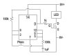
Well, as you're switching 2.4-3.4 AMPs, then that is the reason the schematic uses a MOSFET :D You see standard bipolar resistors are nice and easy to use, but they develop a voltage drop across the emitter and collector (when they are 'switched on'). At 3 amps, this voltage is likely to be quite high, like 0.8V, whichc means the transistor is 'absorbing' 0.8 x 3 = 2.4 Watts, and will get very hot without a heatsink.

MOSFET's on the otherhand, have a 'on resistance' when they conduct. For the MOSFET you're using that is extremely low, around 0.05ohms. Using the equation P = I^2 R (power equals current squared, multiplied by resistance) it will disapate 3^2 x 0.05 = 0.45.

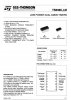
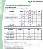
In the data sheet you provided, that gate voltage thresshold is called VGS, and states this is a maximum of 2.0V. This is the minimum voltage needed to 'turn on' the MOSFET so it conducts. Once you're over this voltage at the gate, it will conduct, and the more you go over this threshold voltage, the lower the 'on resistance'. (RDS in the datasheet).

If you look on the table, RDS, which is 'static drain-to-source on-resistance' it shows the resistance of the MOSFET for different gate voltages and drain to source voltages/currents. The lower the gate voltage, the higher the resistance, but...it is still pretty small....60mohms (yes, mili ohms).

So.....ultimately, forget what I said about using a transistor, the MOSFET you have is perfect for that application, and will happily work in that circuit. With a 3.7V supply, the gate voltage will be well....3.7V. So it WILL turn on the MOSFET (its above the 2.0v threshold), but perhaps it will give the MOSFET a slightly higher 'on' resistance.

Sorry for a long and drawn out explaination...I guess I could have said: 'Its fine, the MOSFET is a good idea, and it will work at 3.7V as long as you use a CMOS 555 timer instead of a standard one. - but you wouldn't have learned anything! :D

Blueteeth
 
Hmmm, I wouldn't define less than 0.1V drop for a BJT transistor in saturation as a lot. I've just bought a bunch of CMOS 556's too, so they're out there.
 
Last edited:
Blueteeth> Thank you for the information and I really appreciate it. Other than V=IR, P=VI I do not know anything about electronics/electrical. I am just picking things up from the internet and trying my own DIY stuff. What the resistors and capacitors are doing in the circuit I have no idea. When you guys look at a circuit and do you already know exactly what each component's role is?

I have heard about the MOSFET heating up but as I will be using this LED Light for Scuba diving I guess heat can be dissipated easily through the torch body.

I came across a TS556 and it seems I might be able to do a direct swap. Do I need to change any part of the circuit?
 

Attachments

  • TS556.jpg
    TS556.jpg
    114.7 KB · Views: 1,053
Last edited:
Hmmm, I wouldn't define less than 0.1V drop for a BJT transistor in saturation as a lot. I've just bought a bunch of CMOS 556's too, so they're out there.
To get 0.1V saturation voltage you usually need to run a very high base current. The power wasted in the base resistor can be substantial. There's also a lot of power being dumped into the base-emitter junction itself, which unlike the collector, will be greater than 1V when the transistor is in saturation. The base-emitter junction will be dissipating more power than the collector!
 
To get 0.1V saturation voltage you usually need to run a very high base current. The power wasted in the base resistor can be substantial. There's also a lot of power being dumped into the base-emitter junction itself, which unlike the collector, will be greater than 1V when the transistor is in saturation. The base-emitter junction will be dissipating more power than the collector!

I am not really following this but how will this affect the circuit? By BJT are we talking about the MOSFET?:confused:
 
umibuta,

I believe mneary was merely adding his insight into Quietman's comments about the use if bipolar transistors (or BJT's as they are called) in this circuit. Do not worry, you already have a MOSFET (the one you provided a datasheet for) and that will do a marvelous job. I only mentioned 'bipolar transistors' because occassionally for amateurs who simply want a nice circuit that works, MOSFET's can be a hassle to work with at lower voltages, although, these days many modern MOSFET's (again, such as the one you're using) will happily work at lower voltages.

The TS556 looks fine to me. Works down to 2.0v, which gives you some room to work with, using your 3.7v lithium (which will drop in voltage slightly as it discharges).

So far so good, one quesiton though....it seems in your original schematic, there was no current limiting resistor in series with the LED. What LED are you using? Some LED 'modules' have built-in resistors, or drivers, so they they simply require a 'voltage' to run...where-as bare plain vanilla LED's require limited current to stop them meeting their maker.

All the best,

Buriedcode
 
To get 0.1V saturation voltage you usually need to run a very high base current. The power wasted in the base resistor can be substantial. There's also a lot of power being dumped into the base-emitter junction itself, which unlike the collector, will be greater than 1V when the transistor is in saturation. The base-emitter junction will be dissipating more power than the collector!

Power, yes, current, no. And it will be very low power.

BJT = Bipolar Juntion Transistors, which come in NPN or PNP flavors.

Power isn't usually a problem, and most transistors have a 0.6V BE drop (not 1V), maybe .7V if you push it. A general rule of thumb is 1/10 the base current to guarentee saturation, but this being an approximation, it usually takes a lot less for most transistors.

BJTs are still alive and well. They are my preferred part for most 555 circuits. Like MOSFETs, they have their uses, and in many cases it is only a preferance which is used. I've designed circuits that have flashed 3 months off 2 AAA batteries using BJTs and CMOS 555s.

Even digital level MOSFETS ususally need a minimum of 5V to turn on all the way, but this could be used to compensate for no LED resistor. Problem with that logic is the LED light level will vary a lot.

I agree the OP needs a current limiting resistor, to stabilize things. The LED needs some current limiting of some kind, even if the MOSFET is the primary resistor.

To the OP, are you trying to have a set reset flip flop, or a flasher?

You need pin 4 and pin 10 (the reset pins) connected to Vcc (the + power) for anything to work, these pins can not be left floating.

Here is a template I made for most simple 555 circuits you might find handy.

555-cookbook-gif.35311


When I get a chance I'll redraw your schematic for clarity.
 

Attachments

  • 555 Cookbook.GIF
    555 Cookbook.GIF
    10.5 KB · Views: 9,505
Last edited:
OK, each segment of the 556 is an inverter as drawn. The pizeo designation has me puzzled. I assume you want a switch there, do you want to have a sound when the light is light?

temp1-gif.35314


Do you want me to draw corrections?

You mentioned using a 3.6V battery, are you still wanting a ± power supply, or do you want to run it off 3.6VDC only?

Are you using two 555's, or CMOS 555s, or a CMOS 556? Conventional 555/556's minimum voltage spec is 4.5 VDC, CMOS can go down to 2 VDC. I don't think the MOSFET will work that reliably under 5V.
 

Attachments

  • temp1.GIF
    temp1.GIF
    2.9 KB · Views: 5,214
Last edited:
I missed that part, in post #4. There are ways around it, but he's got bigger problems overall with his batteries, and he still needs a current limit. Sounds like a similar problem I'm working in my other home, might be easier to go with a PuckBuck and use the control input.
 
Blueteeth> Thank you for the information and I really appreciate it.

Most welcome sir.

Other than V=IR, P=VI I do not know anything about electronics/electrical. I am just picking things up from the internet and trying my own DIY stuff. What the resistors and capacitors are doing in the circuit I have no idea. When you guys look at a circuit and do you already know exactly what each component's role is?

Its how I started when I was young. DIY can be annoying at times for a beginner, but its pretty cool to have something useful and say 'I built that from scratch!'. If only women found it attractive.... Resistors and capacitors...well....the internet will tell you what they are, and what roles they can play in circuits. In your schematic you just have a 'block' for the 555 timer IC, likemost schematics, but what exactly the resistor and capacitor are doing...depends on the inner workings of that chip :) Of course, you don't really need to know absolutely everything about the chip but some wonderful sites that can explain its 'magic' better than I ever could are always useful if you are interested:

555 Timer Tutorials - wonderful animation.
555 and 556 Timer Circuits - equally good explaination.
**broken link removed**


I have heard about the MOSFET heating up but as I will be using this LED Light for Scuba diving I guess heat can be dissipated easily through the torch body.

Well, yes, if something is moving underwater, generally it'll naturally have its own cooling. But remember, when something 'heats up', it is converting power to heat. Unless your device is a heater, that energy is considered wasteful. Normal for household appliances, this is generally acceptable, as long as there is adequate heatsinking/cooling, since there is plenty of available power - its just a question of stopping things getting too hot.

But in portable battery powered applications, the heatloss is a sign of inefficiency, so you could be wasting precious battery life. For now, I wouldn't worry about that...everything apart from the MOSFET will hardly draw any current at all.

Now, you mentioned 'LED light for scuba diving'. That tells me you're not just making a small 5mm LED flash. At the current you mentioned, seems like you want a pretty damn bright torch (at 2-3A thats proper blinding!). And its this high current application that has got others fired up about MOSFETsvs transistors :)

Perhaps telling us exactly what kind of LED you are using would help. As I said before, some are just a bare LED (like the big 5W 'star' ones) but many are infact 'modules' which have onboard electronics to precisely control the current through the LED, and allow for it to be powered by varying voltages. (they're usually called 'current mode buck converters').

I'm still confused as to the roll of the piezo, I'm assuming it is some form of 'tap switch', since, underwater, you don't really want exposed switches, and water-proof switches can be a nightmare.

Blueteeth
 
Thanks for all the feedback and circuits :) And my apologies if i cannot provide proper circuits. But I what I do have are these:

I am using the below (attachments):
1) 1.4A AMC7135 circuit to limit the current connected to (2)
2) A 1A output Control Circuit
3) I am using a bare LED Emitter (specifications attached)
4) Toggle Flip Flop Circuit that I have already assembled with the normal 556 chip + LED emitter on heatsink
5) Piezo switch on the tailcap of the torch

Honestly, I am not knowledgeable in electronics hence most parts are bought and self-assembled. I had the Toggle flip-flop circuit (with the normal 556 chip) assembled but it failed when i tried with my the Li-ION battery. I know the circuit is working because it works on 6V (4 x Duracell).

The Piezo switch as I understand turns on for a fraction of a second (I think its called a pulse) which why I need this toggle flip flop circuit to hold the signal and have it work like a normal switch. I am using it because it is sealed and robust, probably suitable for underwater use.
 

Attachments

  • 16ModeCct.jpg
    16ModeCct.jpg
    156.3 KB · Views: 741
  • AMC7135.jpg
    AMC7135.jpg
    236 KB · Views: 795
  • SSCP7.jpg
    SSCP7.jpg
    50 KB · Views: 543
  • togglecct.jpg
    togglecct.jpg
    56.8 KB · Views: 2,646
  • Tailcap.jpg
    Tailcap.jpg
    41.1 KB · Views: 602
Last edited:
Ahh, thats exactly what we needed :)

Ok so, as for the LED part, using your number system '1', limits the current to the driver board '2', (which is says can take 3.6-4.5V). The '2' board,regulates the current to the LED, effectively doing the same job as a power resistor, but with much better stability (constant current source specifically for LED's.

So, going back to your original schematic, that MOSFET will be fine :D as all it is doing is acting like a relay, and letting the boards '1' and '2' do their job of limiting the current to the LED.

I did google the 'piezo switch' after I posted,I haven't heard of them before but they look pretty cool, and perfect for this application - which of course is why you're using it :D

So, as you said, you jsut need a circuit that takes in the short 20-80ms pulse from the piezo switch, and turns the LED either on or of? like a toggle? once for on, once for off?

There are MANY ways to do that, including using a 555 on its own, a 556 (dual 555), a CMOS flipflop, transistors etc...

I believe your circuit comes from this page:
Circuits Page 9 (Relay Toggle Circuit Using a 556 Timer ).

Looks like its all set then, as long as you use a CMOS 555 (again, like the one you posted the datasheet for) then I reckon it sohuld all work :) If you like I'll knock up a test circuit tomorrow and do some test....I'm not working right now, so I have nothing better to do lol

Blueteeth
 
Thanks Blueteeth.

I had just received the Cmos 556 today and everything is working great :D The Mosfet is not as hot as i expected. Other users have feedbacked that the Mosfet was too hot to touch using a normal 556 and 7.2V.

Your website on the 555 is very informative, I bought a dedicated control circuit to toggle the current between high and low for the LED. But after reading about the timer I could use it to toggle between high and low. Seems like a very basic yet useful chip.

Many thanks
Cliff

Yo cliff,

Glad to hear its all working as hoped. I suspect the problem with heating that others are expecting is down to the higher supply voltage used. If the 'modules' you purchased, provided a constant current (which is required for LED's) then they have a particular voltage drop across them. This is the LED voltage (3.7V ish) plus a small voltage used by the current regulator circuit, say 2V. So, because of the 7.2V supply, the module drops 5.7V, leaving....7.2 - 5.7 = 1.5V drop across the MOSFET.

With the LED taking 1A, thats 1 * 1.5V = 1.5 Watts through the MOSFET...which can only be expelled as heat.

With your setup, you're running it right at the lower voltage limit for proper LED operation. This means your battery is providing just enough voltage for it to work, with little overhead that would have to be 'aborbed' by the MOSFET. Thus, itrunns cooler, and is more efficient!

I wouldn't be sirprised if your 3.7V lithium lasts just as long as their 7.2V batteries, with the same capacity. - but you have half the battery size!

Sorry, I know you didn't need to know that, but its pretty cool. You can tell others that your version is more efficient!
 
Last edited:
Status
Not open for further replies.

Latest threads

New Articles From Microcontroller Tips

Back
Top