Electro Tech is an online community (with over 170,000 members) who enjoy talking about and building electronic circuits, projects and gadgets. To participate you need to register. Registration is free. Click here to register now.
Welcome to our site! Electro Tech is an online community (with over 170,000 members) who enjoy talking about and building electronic circuits, projects and gadgets. To participate you need to register. Registration is free. Click here to register now.
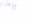
Ok, as i was following the circuit schematic for the four way traffic light from https://www.555-timer-circuits.com/traffic-lights-4-way.html I wired it up in multisim with the 10V 4017BP chip, but for some reason the yellow n/s and red e/w are only lit. Any help would be appreciated, and here is the multisim schematic:
If the other (unlit) LEDs are modelled as white LEDs then 10V won't be enough to drive 4 in series. The forward voltage of a white LED is typically > 3V. BTW using a 12V supply for a 10V-rated IC is not recommended.
I built the exact circuit in multisim using both the 5V and the 10V 4017 and still no luck, and as well as using OR gates/diodes as well and still nothing.
Then there's an error with your sim. The exact circuit in post #7 simulates fine in LTSpice. Note that there are only 2 diodes in series in each circuit branch, so their combined Vf is < 9V.
After switching the leds to all red the circuit works; but here's the specs for the green and yellow diodes; green - Vf - 2.13 V @ 20 mA, yellow - Vf = 1.83 V @ 20mA. So what would be the next step? Also, is there is a way to have to have both branches as individual lights instead of having the red lights flipped?
Yes: you could drive each LED with its own transistor. But why? When NS is green EW is always red, and vice versa (unless you want a safety period when all lights are red).
Ok, after changing the multisim timestep i was able to sim the circuit except for the red and yellow e/w and n/s would alternate but would completely skip the green signals. For the circuit with all red leds, I placed a multimeter on the resistor to ground, base, and collector and i got a reading of ~12.94 mA from the resistor to ground, from the output of the diodes to the base of the transistor I got ~62.44 μA, and from the source voltage to the collector I read ~9.74 mA. When i measured with the original circuit I was reading into the picoamps and microamps at the same spots. Is there a way to beef up the circuit? I tried increasing and decreasing the resistor and capacitor values and no such luck, and also I'd like to have the circuit built in multisim before I construct it so I don't blow something up.
Are you talking about the post #1 circuit or the post #7 circuit?
Do you want an 'all red' safety phase for the lights? Do you want to use individual transistors for each LED?
I can't see any reason why the yellow/green LEDs wouldn't light with the present current, unless their sim models have a problem.
I'll try and come up with a circuit to enable each LED current to be chosen individually.
Here's another Traffic lite circuit.
I didn't adjust the RC for the 555 and you can probably reduce the number of components.
But I left it as is for clarity...
As I read the above truth table the lights will switch directly from red to green with no yellow phase. Is that the way they work in your part of the world eTech? In the UK the sequence is R, R+Y, G, Y, R, .......
I thew the circuit together about midnight last nite...didn't relaize the sequence is different in the UK..
But yes..the sequence in the US is R >G>Y>R>G>Y>R....
This site uses cookies to help personalise content, tailor your experience and to keep you logged in if you register.
By continuing to use this site, you are consenting to our use of cookies.