Fluffyboii
Active Member
Hi,
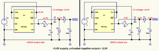
I was trying to make an op amp circuit work from 5V USB power and lack of dual power supply was making it very difficult as always. One way of solving the problem would be using 7660 IC as Nigel suggested. And it seems like a brilliant solution. But I already made an order for electronic parts form an online warehouse and I don't want to make a new order to buy a single IC and pay shipping costs.
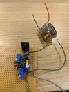
So I was thinking of making some kind of isolated boost converter with the stuff I have at hand. There are multiple ways of getting some kind of AC waveform and feeding it to a transformer to increase its voltage then rectify it. I have decided to use a 555 timer to generate high frequency pulses. Then I could split the AC I get from transformer to get positive and negative voltages as I wanted. I also had a small flyback transformer left from an kit I failed to build some time ago so at worst case scenario it would be used with that. First circuit that comes when Googled is the one at the bottom.

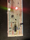
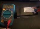
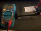
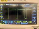
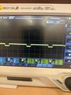
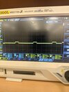
I made it and test it. The frequency was about 1Khz which was too low for driving a flyback but I gave it a go anyway. It consumes about 2A at 3V when flyback transformer is connected because I limited the current so it is not sustainable at 12V. I checked the waveforms at the BJT and it seems like circuit sends some chonky high duty rate pulses to the BJT and it gets inverted to small duty cycle pulses for the Mosfet to do the switching. My choice of mosfet here is IRF630 which I believe should function similarly. The problem is the waveform 555 generates and what shows up at the base of the BJT is quite different. For some reason there is a huge voltage drop at the base of the BJT. In turn it shows up as a very small voltage at collector and at the Mosfet's gate. And I believe because of that reason Mosfet doesn't really do any switching and instead stays open all the time causing huge current to flow. I am putting oscilloscope photos to bottom so you can see how small the voltage gets at the base and collector.
I believed that the 1K resistor was too high and switched it with 100 ohms instead. I also decreased the timing capacitor with 10nF increasing the switching to about 100Khz. This did not change anything. I basically switched to this circuit:

Sooo what I am exactly doing wrong here. I believe 555 part is functioning, BJT is connected right and I did not mixed up the Mosfet connections as well this time. Should I put some series resistance with the gate do decrease current. I actually got some high voltage randomly at the output when I tested it but that was one time only and my 555 blow up later. Now I am sure everything is connected right. If I can get this to work I will use a transformer with small turn ratio and use a bridge rectifier to get my positive and negative rails. If the output signal is full of garbage ripples I will use linear converters to cut it off. Are there any similar oscillator circuits to get a quick dirty AC wave. I doubt lack of feedback will be an issue since my load will be few op amps pulling less than 10mA at total.
The more I think about it stupider it feels that I went with this instead of doing anything else.
I was trying to make an op amp circuit work from 5V USB power and lack of dual power supply was making it very difficult as always. One way of solving the problem would be using 7660 IC as Nigel suggested. And it seems like a brilliant solution. But I already made an order for electronic parts form an online warehouse and I don't want to make a new order to buy a single IC and pay shipping costs.
So I was thinking of making some kind of isolated boost converter with the stuff I have at hand. There are multiple ways of getting some kind of AC waveform and feeding it to a transformer to increase its voltage then rectify it. I have decided to use a 555 timer to generate high frequency pulses. Then I could split the AC I get from transformer to get positive and negative voltages as I wanted. I also had a small flyback transformer left from an kit I failed to build some time ago so at worst case scenario it would be used with that. First circuit that comes when Googled is the one at the bottom.
I made it and test it. The frequency was about 1Khz which was too low for driving a flyback but I gave it a go anyway. It consumes about 2A at 3V when flyback transformer is connected because I limited the current so it is not sustainable at 12V. I checked the waveforms at the BJT and it seems like circuit sends some chonky high duty rate pulses to the BJT and it gets inverted to small duty cycle pulses for the Mosfet to do the switching. My choice of mosfet here is IRF630 which I believe should function similarly. The problem is the waveform 555 generates and what shows up at the base of the BJT is quite different. For some reason there is a huge voltage drop at the base of the BJT. In turn it shows up as a very small voltage at collector and at the Mosfet's gate. And I believe because of that reason Mosfet doesn't really do any switching and instead stays open all the time causing huge current to flow. I am putting oscilloscope photos to bottom so you can see how small the voltage gets at the base and collector.
I believed that the 1K resistor was too high and switched it with 100 ohms instead. I also decreased the timing capacitor with 10nF increasing the switching to about 100Khz. This did not change anything. I basically switched to this circuit:
Sooo what I am exactly doing wrong here. I believe 555 part is functioning, BJT is connected right and I did not mixed up the Mosfet connections as well this time. Should I put some series resistance with the gate do decrease current. I actually got some high voltage randomly at the output when I tested it but that was one time only and my 555 blow up later. Now I am sure everything is connected right. If I can get this to work I will use a transformer with small turn ratio and use a bridge rectifier to get my positive and negative rails. If the output signal is full of garbage ripples I will use linear converters to cut it off. Are there any similar oscillator circuits to get a quick dirty AC wave. I doubt lack of feedback will be an issue since my load will be few op amps pulling less than 10mA at total.
The more I think about it stupider it feels that I went with this instead of doing anything else.
Attachments
Last edited: