ThomsCircuit
Well-Known Member
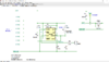
R3=560K
C1=47u
VR1= 1M
I want to know if i have connected the Resistor, cap, trimpot correctly.
The design of this circuits time delay range is 0 - 60 seconds.
It should be 30-60 seconds.
Did i connect something wrong or is this normal?
Does it matter how R and C connect to VR?
C1=47u
VR1= 1M
I want to know if i have connected the Resistor, cap, trimpot correctly.
The design of this circuits time delay range is 0 - 60 seconds.
It should be 30-60 seconds.
Did i connect something wrong or is this normal?
Does it matter how R and C connect to VR?
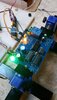
Attachments
Last edited: