MrDEB
Well-Known Member
Have seen this done before and feel it's wrong as a 555 will not operate properly.
also will the 555 output drive a second 555??
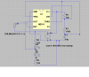
Model Railway Level Crossing Lights Project
the output of the second 555 provides power for the third 555
am I right in my thinking or just half cocked??
also will the 555 output drive a second 555??
Model Railway Level Crossing Lights Project
the output of the second 555 provides power for the third 555
am I right in my thinking or just half cocked??