Continue to Site

Welcome to our site!

Electro Tech is an online community (with over 170,000 members) who enjoy talking about and building electronic circuits, projects and gadgets. To participate you need to register. Registration is free. Click here to register now.

  • Welcome to our site! Electro Tech is an online community (with over 170,000 members) who enjoy talking about and building electronic circuits, projects and gadgets. To participate you need to register. Registration is free. Click here to register now.

555 not timing,what am I doing wrong?

Status
Not open for further replies.

markelectro

New Member
Hello to all

I have a 555 timer circuit that I can't seem to get timing.

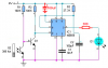
The circuit is using a trigger from an LED. and a photo transistor.The use of this circuit is for one of my other threads-

https://www.electro-tech-online.com/threads/1-sec-pulse-from-30-sec-clock.31429/#post235809

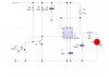
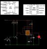
Basically when a pendulum swings in a clock it will break the beam of light to the light sensor (photo transistor) when this happens the the 555 will run for a given amount of time sending power through to an external device.For the purpose of the experiment I used and LED. for the external device.This does happen but the 555 does not time out.I want the 555 to time out after about 3 sec's.

When the transistor is receiving the light then the circuit runs ok (no power going through to the external device)

Due to my lack of electronics knowledge I am now at a loss.I have been at this for hours trying to get it to work.

Can you please Help?

Regards Mark
 

Attachments

  • torbans circuit 2.jpg
    torbans circuit 2.jpg
    57.5 KB · Views: 198
  • torbans circuit.jpg
    torbans circuit.jpg
    63.6 KB · Views: 230
The timining resistor and capacitor should be chosen according to this formula: T = 1.1 R C; for 3 s you can use 68kΩ and 47 uF, for example. As you know, tolerances affect the ideal behaviour.
You didn't placed a current limiting reistor at pin 3.
Have you checked the output with a multimeter, without the LED?
 
eng1 said:
The timining resistor and capacitor should be chosen according to this formula: T = 1.1 R C; for 3 s you can use 68kΩ and 47 uF, for example. As you know, tolerances affect the ideal behaviour.
You didn't placed a current limiting reistor at pin 3.
Have you checked the output with a multimeter, without the LED?


Thanks eng1

I did as you sugested and put a multimeter inplace if the LED. and when no light going through to the transistor the meter shows the 9v that is flowing through the circuit.

regards mark
 
IRL3103 said:
There are 2 free programs to calculate 555 timer components. SS55511.exe and ic_555.exe.


Hey thanks for that.!!!!

Sorted!!! I just put into the 555 calc what I wanted and it gave me a workable capaciter and resistor.

Cheers.

Mark
 

Attachments

  • 555 timer working correctly.jpg
    555 timer working correctly.jpg
    44.2 KB · Views: 185
heres a simple edge triggered 555 schematic i built a while back-it should give you a few pointers how to go about using the 555 another way.........
 

Attachments

  • TIMERRELAY.pdf
    22.7 KB · Views: 185
Markelecto, I agree with eng1 you still need a current limiting resistor in series with the LED on pin 3. I have also found that most electrolytic capacitors greater than about 10uF cause timing problems because of the leakage current. A better solution is use a higher value of resister in the timing calculations.

Sheldorstv, your diagram for your circuit should have about a 1K resistor in series with the 1M pot if the pot is adjusted near 0 ohms the current to pin 6 and 7 could exceed maximum value.
 
Hi all

Been palying around with it and if I put a resistor of 560 or 680 then the led does not light but if I go down to 1k then it does light up.

Now I am confused.:confused:

Regards Mark
 
I got rid of the awful black background, added a supply bypass capacitor and added a current-limiting resistor for a red 2V LED.
 

Attachments

  • 555 and LED.PNG
    555 and LED.PNG
    44.3 KB · Views: 198
markelectro said:
Hi all

Been palying around with it and if I put a resistor of 560 or 680 then the led does not light but if I go down to 1k then it does light up.

Now I am confused.:confused:

Regards Mark
Lower the resistor, brigther the LED. Did you a use 560 ohm resistor? I expect the LED current to be about 10 mA with a 560 ohm resistor. That's reasonably enough?
 
All

By jo I think I got it!!!

Cheers eng1 for that.I got my resistor values mixed up.

You will now see the led. glowing like a light house.thanks to :eek:hm: :D

Cheers audioguru for the new schema!!! I added mine a logic level just so you all could see the flow.I am now very happy to see it up and running corectly.I THINK!!!

Regards Mark
 

Attachments

  • audioguru circuit.jpg
    audioguru circuit.jpg
    36.4 KB · Views: 166
Hi Mark!

Glad to see you've got the sim working! Sorry I didn't have time to answer your earlier post in the original thread earlier today.


Good luck with the project!

Torben
 
Torben said:
Hi Mark!

Glad to see you've got the sim working! Sorry I didn't have time to answer your earlier post in the original thread earlier today.


Good luck with the project!

Torben


Hey Torben :D


Cheers for that.It took a while to get the little circuit going but I did learne a lot doing so.

Cheers Mark
 
yes you are quite right........there should be a resistor fitted..........
 
Status
Not open for further replies.

New Articles From Microcontroller Tips

Back
Top