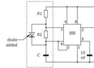
This can be done easily with just two 555's, or with one quad gate package as in post #6. However, that circuit is for driving a bare piezo element, not a complete beeper. It uses two oscillators to make the beeper go on and off continuously, not in groups of beeps separated by off-times. However, the approach of one oscillator controlling another oscillator is correct.
BTW, CMOS logic circuits are extremely efficient, using only a few microamps to operate.
Either with two 555's or two oscillator circuits, have one oscillator drive the beeper at the rate you want the beeps to happen in a burst, such as five beeps in one second. The second oscillator gates the first one on and off. This sets the time between beep bursts. This type of gated beeper is pretty common, and uses very few parts.
Are you familiar with the CD4093? This is a quad NAND gate, but the gates have Schmitt trigger inputs. Not only do they work much better than a 4011 with low frequency circuits, but you also can get an oscillator in only one gate.
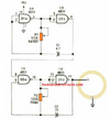
Here is a first pass at a gated beeper circuit. U1A forms an oscillator with a period of approx. 2 seconds. That's one second of rapid beeping and one second off. Its output gates U1B on and off. U1B is an oscillator with a period of approx. 0.2 seconds. That's five beeps in one second, the time it is gated on by U1A.
U1C inverts the logid polarity out of the U1B oscillator. When U1B is gated off by U1A, its output sits high. Since you want the beeper to be gated off rather than on-steady, that high must be converted to a low before driving the output transistor.
U1D is a spare gate. Its inputs have to be terminated either high or low, not just left floating. They can be tied to just about anywhere in the circuit.
View attachment 144997