Hi folks.
Today I was asked to come up with a method of switching between a calibration mode and an operation mode for a test apparatus.
The current situation is that the operations technician, who must periodically certify the temperature calibration with a 100 Ω standard probe simulator (decade box), also must remove the cover of the apparatus and remove the main circuit board to access the sensor connections for his procedure.
Our company policy is that any procedure that requires gaining access to circuits with potentially hazardous voltages (ie cover removal) must be performed by qualified personnel. This would be myself, an Instrumentation technician, or an Electrician. However, calibration procedures (such as this) are typically handled by operations personnel, but this is a rare instance where external provisions for calibration are not made (design flaw).
The equipment in question has two identical circuits with two seperate temperature sensors. The sensors are the components that are certified by resistance simulation. The decade box is connected in place of the sensor and variable resistances (i.e. known reference temperatures) are presented to the control circuits. The apparatus is deemed serviceable if the control circuits agree with the decade box. Another procedure involves a calibrated hot/cold source with the sensor submerged, but that is not material here.
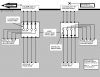
At any rate. I have drawn up a schematic for two 4P2T switches and connectors to be mounted on the enclosure and wired for external calibration. This will eliminate the need to remove the cover.
In my mind, this is the easiest approach, but it would be nice to have a single switch and a single connector. The only problem in my mind is the spaghetti factory that the wiring would require. I'm not even sure what kind of switch would work. 8P2T?
I was hoping forum members might give me a critique, note any difficiencies in my drawing, and suggest improvements. This will be submitted to electrical engineers at the apparatus factory as well as my management for review.
Thanks for the help in advance.
Today I was asked to come up with a method of switching between a calibration mode and an operation mode for a test apparatus.
The current situation is that the operations technician, who must periodically certify the temperature calibration with a 100 Ω standard probe simulator (decade box), also must remove the cover of the apparatus and remove the main circuit board to access the sensor connections for his procedure.
Our company policy is that any procedure that requires gaining access to circuits with potentially hazardous voltages (ie cover removal) must be performed by qualified personnel. This would be myself, an Instrumentation technician, or an Electrician. However, calibration procedures (such as this) are typically handled by operations personnel, but this is a rare instance where external provisions for calibration are not made (design flaw).
The equipment in question has two identical circuits with two seperate temperature sensors. The sensors are the components that are certified by resistance simulation. The decade box is connected in place of the sensor and variable resistances (i.e. known reference temperatures) are presented to the control circuits. The apparatus is deemed serviceable if the control circuits agree with the decade box. Another procedure involves a calibrated hot/cold source with the sensor submerged, but that is not material here.
At any rate. I have drawn up a schematic for two 4P2T switches and connectors to be mounted on the enclosure and wired for external calibration. This will eliminate the need to remove the cover.
In my mind, this is the easiest approach, but it would be nice to have a single switch and a single connector. The only problem in my mind is the spaghetti factory that the wiring would require. I'm not even sure what kind of switch would work. 8P2T?
I was hoping forum members might give me a critique, note any difficiencies in my drawing, and suggest improvements. This will be submitted to electrical engineers at the apparatus factory as well as my management for review.
Thanks for the help in advance.
")
