Continue to Site

Welcome to our site!

Electro Tech is an online community (with over 170,000 members) who enjoy talking about and building electronic circuits, projects and gadgets. To participate you need to register. Registration is free. Click here to register now.

  • Welcome to our site! Electro Tech is an online community (with over 170,000 members) who enjoy talking about and building electronic circuits, projects and gadgets. To participate you need to register. Registration is free. Click here to register now.

4kw Motor Conversion

Status
Not open for further replies.

bryan1

Well-Known Member
G'day Guys,
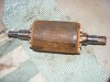
Well I scored a nice 4kw motor perfect for a motor conversion yesterday at work for free. The motor was stuffed as moisture got in so I'm currently in the process of ripping out the wire and I'll do a total re-wire using thicker wire and so it's suits my 24 volt array.

motor.JPG

The wire in it presently is 0.8mm and I will going for thicker wire hopefully 1.2mm but it will depend on how many turns I'll need in each slot. I'll make a new solid steel rotor to hold 60 off 1"x1/2" neo magnets with 15 in each pole. The conversion will have 12 wires coming out so that will give plenty of wiring options.

I'll upload pic's as I go on this conversion to provide a good guide on converting a 3 phase motor to a wind generator.
1 delta
1 star
2 delta
2 star

So depending on the conditions it will be easy to change the wiring setup to get the optimum configuration. I reckon 3 metre blades will be perfect for this so now the hunt is on to find some nice straight grain oregon wood for them.

Cheers Bryan
 

Attachments

  • nameplate.jpg
    nameplate.jpg
    198.5 KB · Views: 935
  • rotor.jpg
    rotor.jpg
    166.2 KB · Views: 927
It's a nice lightweight but strong Australian hardwood.

Nice work Bryan! Looks like that drive side bearing was rusted on pretty good. Bet you took the oxy to it to get the bearings off...
 
It's a nice lightweight but strong Australian hardwood.

I checked several Australian wood suppliers and could not find "oregon" as a common name for any wood.

Do you happen to know any other names for it? Are you perhaps referring to Ramin?

John
 
I really don't know if that's the right spelling, but that's how they say it. I'm not a wood guy. :) I do know it's nothing exotic, last time I bought a door jamb it was oregon and it was not much dearer than pine.
 
First off, I am interest in woods. Maybe bryan1 will enlighten us on it.

My other reason, is that a 3M propeller blade is not a toy. I wonder why bryan1 isn't looking at composites, like Burt Rutan has used in many of his aircraft designs. Just cut from foam, cover with carbon fiber/epoxy, and vacuum bag. That gives a stronger and lighter product than wood. It is also quite easy to get the right airfoil consistently across the chord of the blade.

John
 
G'day John,
Oregon was used for houses here in the early years, it's a hardwood and one can find nice slabs perfect for carving blades cheap at scrap yards. I made a 3 metre set for my 1.5kw conversion ages ago and they are still going strong. I'll probably use those 3 metre blades on this conversion and make a new 2 metre set for the 1.5kw genny.
Hopefully later today I'll get the last of the wire out of the motor then it's time to start machining the new rotor. It will be awhile before I can do much more as I will need to source the neo magnets from the US.

Cheers Bryan
 
G'day Guy's,
Well finally got all the wire out of the motor, so the job now is to design and make the rotor. Last night I spent some time on autocad to workout the best configuration of magnets for each pole. Basically each pole is 70mm x138mm and will have a 10 degree skew to eliminate any cogging. First I tried with 3/4" round magnets but I could only fit 15 in each pole and the spacing seemed too big. I then tried 5/8" and I got 32 to fit in the space nice and snug.

4kw mag positions.JPG

I checked pricing on the magnets with Applied Magnets who I bought my last set of neo magnets off and the 5/8" x 1/2" round neo's are only 60 cents US each. So that will workout cheaper than the 3/4" ones for more magnet area on the rotor.

Today I got the slot insulation paper so hopefully this weekend I'll get the motor all cleaned up and all the slot insulation installed. Then the stator will be ready for the 1 turn test once the rotor is finished.

Cheers Bryan
 
Bryan, how much can you reduce cogging without the generator power output suffering?

Like if you have armature N and S magnet poles going past the stator pole at the same time that reduces cogging but will also reduce output power. And if you have all the N magnet poles going past the stator pole at the same instant you get maximum output power but also maximum cogging.

Hi Roman,
In my last post the picture shows the magnets at a 10 degree angle, for a 36 slot motor 10 degrees is used so only 1 magnet is directly over the path of the coil at any one time. This if done correctly will get rid of any cogging fully, the output won't suffer at all. The main reason to do a full rewind is to get the optimal cutin at a preset voltage/rpm. I will be aiming for 24 volts @ 150 rpm. This will let the blades get up to speed before the load cuts in and the power of the wind will keep the blades going. If the cut in is too low the wind wont have enough energy to power the blades so the blades will stall.

Cheers Bryan
 
First off, I am interest in woods. Maybe bryan1 will enlighten us on it.

My other reason, is that a 3M propeller blade is not a toy. I wonder why bryan1 isn't looking at composites, like Burt Rutan has used in many of his aircraft designs. Just cut from foam, cover with carbon fiber/epoxy, and vacuum bag. That gives a stronger and lighter product than wood. It is also quite easy to get the right airfoil consistently across the chord of the blade.

John

Probably not the same but in South Africa what we call "Oregon Pine / Wood" is the Douglas Fir and yes it was used extensively for floors etc. Here the wood used for cottage / rustic style furniture. Unfortunately normal pine here is being stained to emulate "Oregon". Our fir trees grow faster the grain is coarse and the wood much softer than the Dougla Fir.

Cheers
 
One real concern I would have with the motor conversion is the RPM drop Vs realistic power output capacity.

A 4 KW motor is only 4 Kw output at around 1440 RPM (4 pole 1500 RPM synchronous speed) or what ever its name plate was rated at. If you drop the RPM's down the output capacity drops proportionally. At 150 RPM it would only be a 400 watt motor assuming no slip losses or other factors. If it was a two pole motor that ran at around 2880 RPM at 150 RPM it would only be about at 200 watt motor.
A 3 M rotor around my part of the world would easily and regularly top over 3 - 4 KW at high winds.

I am working on a similar magnet conversion in order to run an old 7.5 Kw motor as a direct drive generator with a 2.5 M blade set.
It will run at around 500 - 600 RPM peak which equates to an estimated motor output capacity of about 2 - 2.5 KW continuous and should hold surges up to about 3.5 Kw for several minutes. (its a rather robust old motor with a high service factor of about 1.4):)

I do not know what the efficiency of a home made permanent magnet conversion is but I suspect it may not yield the same magnetic flux densities that the motor originally had when line powered.
Good high powered neodymiums still fall short of what good quality electromagnets can do in terms of flux densities and related magnetic power in general when compared to whats common inside an induction motor.

You may get the name plate amps output at the motors rated speed but it could fall short on the actual output voltage at that amp draw resulting an even lower effective power output capacity. Changing winding ratios and operating speeds could possibly leave you with something far short of what the ideal ratios would indicate.
 
Thanks for explaining that Bryan. So the 10 degree offset is about the max you can use without the stator pole being exposed to both N and S magents at the same time, or at least with minimum overlap. That's clever.

I'd like to see photos of your rotor. Is it worth separating N and S magnets with grooves (obviously at 10 degrees too) which encourages magnetic path through the stator poles? Although cutting 10 degree grooves down the full length of the rotor is not going to be a fun job...
 
Tcmtech,
The whole point of doing the rewind is I'll be doing a 1 turn test first ( thats 1 wire in the slot), running the setup in my lathe at 150 rpm then measuring the AC volts of the single turn. As coil turns are a ratio to voltage the voltage I get doing the test will dictate the turns I need for 24 volts. The motor originally had 124 turns of 0.8mm wire in so off that I can workout the slot fill then after the test and I know the amount of turns I need will dictate how thick of wire I can go to get the maximum current out.
Hopefully soon I can machine the new rotor at work then I have the fun job of counter boring 128off 5/8" pockets in the rotor at the 10 degree spacings. That job may yet be done in a cnc machine depending if my mate has the time to do it or I'll do it in my bridgeport using my dividing head. Today I did an update on my website with this conversion and there I'll do a full report on every aspect of this conversion.

This idea of motor conversions isn't mine a bloke named 'Zubbly" in the RE world developed this convention. Unfortunately he died a couple of years ago and I'm doing my best to follow on from his work.

Cheers Bryan
 
I am just trying to understand the converting ratios that would dictate what size of motor will make what size of PM alternator at what percentage of its original RPM ratings.
Overall I am curious to see what the actual working efficiency is of a PM conversion. I have plans to do several myself all using large industrial motors.

I am simply stating the basic relationships of speed to power ratios I am familiar with on regular variable speed motor and alternator applications.
Given the blade diameters will dictate the upper power capacity and speed rates I am simply curious as to how a motor with this type of conversion will work in wind conditions that can realistically over drive the windings or cause too much rotor slip and generate too much internal losses from the motor just being too small.

Ive seen enough home made units crash and burn or just fly apart from the generator system simply being too undersized to be able to control the power available in a higher wind situation. Depending upon what type of speed control system you use there is going to be a limit to what the generator can produce with out damage.

I prefer to build my systems with considerable mechanical and electrical robustness and simply let dynamic loading do most of the speed limiting.(yet several still had overdrive problems at times.)
If the blades can safely catch 4 KW in a high wind I want a generator that can safely hold 4 Kw of load at the same time. Having a 400 watt capacity generator that requires a speed limiting or furling system that prevents the blades from ever producing more than 10% of their peak capacity seems like an inefficient use of the potential energy available.
 
G'day Guys,
Well it has been awhile since I worked on this project, however, this weekend i've started putting the magnets on the rotor and epoxying in each pole when all the magnets are in. I currently have 3 out of the four poles installed but the pic only shows one pole installed.

4kw rotor first mags.png

I machined 21 counterbores for each pole and when I hear that click where the magnet seats in the counterbore I know I can let it go and it will stay there. Once all four poles are in I'll wrap some glass cloth around the OD then put the rotor in a mold and epoxy the rotor so I can then machine the final OD to be 1mm smaller than the motor bore.

In the next few weeks I'll be doing the one wire test and I'll keep this thread updated with my progress.

Regards Bryan
 
G'day Guy's,
Well my 4kw conversion is one step closer to being finished and I have done a complete blog on it on the Another power forum

https://www.anotherpower.com/board/index.php/topic,615.0.html

Next week the motor will be off to the motor rewinders as I do want a professional job done and I am happy to say this job is beyond me.

Cheers Bryan
 
Status
Not open for further replies.

Latest threads

New Articles From Microcontroller Tips

Back
Top