Continue to Site

Welcome to our site!

Electro Tech is an online community (with over 170,000 members) who enjoy talking about and building electronic circuits, projects and gadgets. To participate you need to register. Registration is free. Click here to register now.

  • Welcome to our site! Electro Tech is an online community (with over 170,000 members) who enjoy talking about and building electronic circuits, projects and gadgets. To participate you need to register. Registration is free. Click here to register now.

4060 1hz Oscillator not working

Status
Not open for further replies.

dude_500

New Member
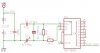
I'm trying to build a 1hz Oscillator using a 4060 and 32.768khz, then a 4013 divider to take the 2hz to 1hz.

Here is my schematic http://www.mcamafia.de/nixie/images/nix_1hz.jpg

It seems like depending on the variable capacitors value, the output on either pin 3 of the 4060 (should be 2hz) or pin 1 of the 4013 (should be 1hz) is either on or off, but not oscillating. I'm testing with an LED.
 
Do you have 100nF capacitors connected across the supply rails of each IC?
 
I just put a cap on the positive rail of the 4060, still doesn't seem to be oscillating. I'm not even using the 4013 divider right now, I can't even get a 2hz out of the 4060.
 
Your circuit does not have a power supply voltage listed. What is it?
 
I've been running it on 5V, but also tried a 9V battery just to make sure it wasn't below a threshold. According to the datasheet it should work down to 3v.
 
The datasheet shows a much higher resistor value (330K)across the crystal, where your circuit has 2K. Your crystal may be loaded down.

https://www.fairchildsemi.com/ds/CD/CD4060BC.pdf
The 330k resistor in the datasheet and the 2.2k resistor in the OP's circuit is not across the crystal. It is in series with the crystal to reduce the current so that the fragile crystal doesn't shatter.
 
Last edited:
The 330k resistor in the datasheet and the 2.2k resistor in the OP's circuit is not across the crystal. It is in series with the crystal to reduce the current so that the fragile crystal doesn't shatter.

Indeed it is in series from a DC perpective. From an AC equivalent perspective, it is in parallel. So, if the increased drive from the 2.2K is not great enough to shatter the crystal, it may still be too great a load on the crystal to allow sustained oscillation.
 
Indeed it is in series from a DC perpective. From an AC equivalent perspective, it is in parallel.
No it is not in parallel.
It is in series from the input of the driving circuit to its output.

The very high value resistor is in parallel with the crystal (in series with the lower value resistor). Its value is high enough that it does not load down the crystal.
 
No it is not in parallel.
It is in series from the input of the driving circuit to its output.

Yes, and when you include the impedance in the driving circuit from input to output, the other end of the 2.2k resistor is connect to the input of the driving circuit through that impedance. The combined impedance of the driving circuit in series with the 2.2K resistor is in parallel with the crystal.
 
See the difference?

Boncuk
 

Attachments

  • 2Hz-OSCI.jpg
    2Hz-OSCI.jpg
    26.2 KB · Views: 2,407
I built boncuk's circuit and it doesn't oscillate... I'm assuming that an LED on pin 3 to ground should be blinking twice a second.
 
Here is a crystal oscillator and an article about it:
https://www.electro-tech-online.com/custompdfs/2009/02/AN-340-1.pdf

From the appnote:

R1: Isolates the crystal network from the gate output and provides excess phaseshift decreasing the probability of spurious oscillation at high frequencies. Value should be approximately equal to input impedance of the crystal network or reactance of CB at the oscillator frequency. Increasing value will decrease the amount of feedback and improve stability.​

Using CB of 100pf and 32.8 KHz, R1 would be 48.5K from the above, which is more than 20 times the 2.2K resistor. The other circuit elements do come into play to form the impedance of the crystal network, but CB is dominate since the output impedance of the gate is likely quite low. If R1 is too low it will load the crystal network further and cause instability, if not damage it.
 
I built boncuk's circuit and it doesn't oscillate... I'm assuming that an LED on pin 3 to ground should be blinking twice a second.

If the LED current is high you won't see the LED blinking. Use either a low current LED (IF=2mA) with a current limiting resistor of 1K4 (for 5V supply voltage) or use a low power transistor such as 2N2222 to drive the LED.

Alternatively you might try a one second timer circuit which uses just one IC.

Boncuk
 

Attachments

  • 1-Hz-Time-Base.gif
    1-Hz-Time-Base.gif
    23.6 KB · Views: 3,912
Last edited:
Post script

If you study the CD4060 data sheet you will be surprised about the capabilities of the chip.

At a supply voltage of 5V it can drive 1.1mA or sink 0.36mA, far too low to drive an LED.

Please proceed as already suggested.

Boncuk
 
I would have expected it to be the other way round - P MOSFETs have a higher resistance than N MODFETs.
 
Status
Not open for further replies.

Latest threads

New Articles From Microcontroller Tips

Back
Top