Continue to Site

Welcome to our site!

Electro Tech is an online community (with over 170,000 members) who enjoy talking about and building electronic circuits, projects and gadgets. To participate you need to register. Registration is free. Click here to register now.

  • Welcome to our site! Electro Tech is an online community (with over 170,000 members) who enjoy talking about and building electronic circuits, projects and gadgets. To participate you need to register. Registration is free. Click here to register now.

40174 ic with 555 as clock funny behaviour.

Status
Not open for further replies.

neptune

Member
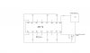
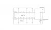
Just for fun i connected 40174 Ic's clock input from 555 Astable mode output.
But the problem is any of the output LED's glow up without even being connected to any Logic 1 or 0. LED's light up and down randomly without sequence.
I think this maybe because i left inputs open. But what shell i do??.
Also one thing when LED's are on they flicker with 555 frequency , Though i connected Decoupling capacitor so that it does not happen.
 

Attachments

  • 40174ring.jpg
    40174ring.jpg
    35.5 KB · Views: 1,127
I think this maybe because i left inputs open.
In general unused digital inputs (in this case all of them...) need to go somewhere, either ground or Vdd. So... correct.

Also one thing when LED's are on they flicker with 555 frequency , Though i connected Decoupling capacitor so that it does not happen.
The decoupling capacitor filters power supply noise, not the device clock. Of course the LEDs would flicker with respect to the 555 CLK input, the clock transitions are bringing in the new bit states. Since your inputs are floating each clk pulse will cause to LEDs to have an indeterminate state or "randomly without sequence. " as you put it.
 
There are many mistakes:

The 9V battery plus must go direct to Vcc on the '174 , and to the 555. The battery minus must go to Vss on the '174 and to GND on the 555.

The 40174 is not a counter, it is just 6 flops with a common clock. To make it do something useful, you would have to turn it into a shift register or a counter. Even if you turn it into a counter, the oscillating frequency of the 555 must be less than 20Hz, or all LEDs will seem to light dimly.

Each LED must have its own current limiting resistor. All CMOS inputs have to be tied either to ground, Vcc, or another CMOS compatible output.
 
A Cmos 555 should be used because an ordinary 555 causes 400mA supply current spikes that upset logic ICs, especially when a low current 9V battery is used.
 
revised schematic


how do we find out that 555 is CMOS or other. i used LM555CN but could not find anything in datasheet.

i will test the circuit with inputs tied down.
 

Attachments

  • 40174.jpg
    40174.jpg
    36.4 KB · Views: 1,208
Last edited:
You still have all the same problems as you had before yourevised the schematic.
 
i will test the circuit with inputs tied down.

With all respect, I would suggest you first review the fundamentals of blinking a LED using a 4011 chip driven by a 555 astable oscillator. Once you have mastered that truth table, you will be prepared to move on into more complex chips such as a D flip flop.
 
An NE555 and LM555 are ordinary high current ICs.
LMC555, TLC555 and ICM7555 are Cmos low current ICs.

The datasheet for the LM555 shows that two decoupling supply bypass capacitors are needed. The 0.1uF ceramic capacitor smooths high frequencies and a 1uf to 100uF electrolytic smooths lower frequencies.

Get rid of the useless 1k resistor at the battery. When the 555 tries to conduct 400mA then the supply voltage to the 40174 drops to zero.
 
I have connected 0.1uF & 100uF capacitor through 555 chip power supply.Input to 40174 are tied down to high.
But still LED's are flickering.
555 timer is giving me nuts.
I suppose what kind of IC is this that creates glitch in power supply ?
 
Your ordinary 555 creates 400mA supply current spikes because it is powerful and its output switches quickly.
Your 1k resistor feeding 9V to the circuit makes it much worse.

Why not use a CD4017 sequencer IC instead of the CD40174 flip-flops IC?
 
I am not making sequencer.i already did that.
I also removed 1K resistor.
I just wanted to store input bits in chip like 40174.
But I think whats the use 40174 when its input needs fix logic to either high or low.
It doesn't work like it was suppose to work, a clear D- F/F.
A real memory chip should be able to store bits when input logic are gone.
Is there anything i can do. should i remove 555 with simple bistable transistor oscillator ?
 
well this was the thing i thought of making.
this is its block diagram
 

Attachments

  • qet.png
    qet.png
    12 KB · Views: 313
Last edited:
The CD40174 is a 6 bits memory chip. Each flip-flop stores the logic level at its D-input when the clock goes high.
But your 555 is a clock oscillator so if the D-input changes then the output of the flip-flop also changes each time the 555 goes high.
If you stop the clock oscillator then each flip-flop will store the logic.

Your LEDs light only for a logic low at the outputs and turn off for a logic high.
 
i didn't knew you were on other site also.
lol.
 
i made few corrections.
this is just a block diagram of it.
what i have done is that i have separated 555 IC from 40174, with the help of 4017 decade counter.
it will count very fast until 10 so that there is continuous clock signal to 40174.
because input data will be coming continuously changing one after other, so 40174 is always ready to store.
 

Attachments

  • qet2.png
    qet2.png
    12.9 KB · Views: 444
Status
Not open for further replies.

Latest threads

New Articles From Microcontroller Tips

Back
Top