Continue to Site

Welcome to our site!

Electro Tech is an online community (with over 170,000 members) who enjoy talking about and building electronic circuits, projects and gadgets. To participate you need to register. Registration is free. Click here to register now.

  • Welcome to our site! Electro Tech is an online community (with over 170,000 members) who enjoy talking about and building electronic circuits, projects and gadgets. To participate you need to register. Registration is free. Click here to register now.

3w led and resistor help

Status
Not open for further replies.

gizmo13

New Member
Hello all,

I am making a chaser light unit for my car and I am planning on using a 3w led. To be more specific it's a "knight rider" type of construction. The 3w led's are going to be used on the light bar only and not the control unit.
I have used a website called ledz.com which has an automatic resistor calculator.
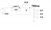
I typed all the info: 14v, 2.2 voltage drop with 700 mA and it gave me a resistance
calculation of 16.857 ohms.
Is this correct??????


Craig
 
Hi gizmo13, I'm kind of dealing with the same thing, except I'm using a 10 W 12.6 v 800 ma LED, the trouble you will probably run into is that the voltage on cars varies, you have ~ 12.6 without the engine, ~ 13+ after you start the engine and ~14.4 with the engine revved up. What I would suggest is use a current regulator made form a LM317, you can probably series 3 or 4 per LM317. Take a look at my post, you'll how I limited the current, trouble is, I had to have a higher voltage to make the regulator work, but I got it.
Kinarfi
 
Craig, the resistance is correct. You maybe should allow for 14.4 V, which takes the resistance to 17.4 ohms, or just use an 18 ohm resistor which actually exists. You need a resistor rating of at least 10 W.

I would use one of these:-
WELWYN|WH25 18R JI|RESISTOR, 25W 5% 18R | Farnell United Kingdom
and bolt it down to a flat area of metal on the car.

Using a resistor is a very simple way of controlling the LED current. It has the advantage of simplicity and it is robust. There will be a small variation in current as the voltage varies from 12 V to 14.4, but that is not likely to be noticeable.

The downsides of using a resistor are that the current can't easily be adjusted, but it will vary a bit with voltage. It is also very inefficient, with only 16% of the power taken from the supply going to the LED, and 84% going to the resistor.

A buck current regulator will be far more efficient, the current will not vary, and you can adjust it if you want. However, it is much more complicated and expensive.

**broken link removed**
 
Thanks guys. Will tinker with this information in the next week.
craig
FYI, a 1.5 ohm, 3W resistor in series between the LM317s out and adjust gives me 825 ma on each of 3 om LEDs.
 
FYI, a 1.5 ohm, 3W resistor in series between the LM317s out and adjust gives me 825 ma on each of 3 om LEDs.

Are you using 1 LM317 for EACH LED, or one LM317 for ALL your LEDs?

Say, if you had 2x 3w LEDs that need 700ms of current, should they be wired in series, and the regulator set to 1.4a?

I also am working on some projects using just that, 3W LEDs.

Thanks,
Andrew
 
With my 10 watt LEDs, they need 800 ma at 12.6 volt and the LM317s need about 2 volts head space to operate, so I had to up my voltage to 18+ and I am using 1 LM317 per LED. How ever, using the 3 watt LED 3.6 volt/LED at 700ma and assuming 12.6 automotive when the engine is off and 14+ when the engine is running, You can series 3 LEDs and 1 LM317 with a 1W 2 ohm resistor paralleled with a 1/4 or 1/8 W 16.9 ohm resistor to obtain the rated 700ma.
 

Attachments

  • 800 ma LM317.png
    800 ma LM317.png
    33.1 KB · Views: 907
Thank you kinarfi, that was helpful.

Andrew
 
what are you using them on?
 
Hopefully, to retrofit my 1982 K5 Blazer's tail/stop light from incandescent to LED.

Also changing backup lights to very bright LEDs for better illumination.

Andrew
 
I think you're going to be surprised how bright these are, I would suggest you use the drawing I supplied, but just use the 2 ohm resistor and don't bother with the 16.9 ohm, you'll still get plenty of light and be operating a bit below max. Don't know which LEDs you ordered, but reds would be best, but whites will work with the red lense. Got another drawing coming to cover the dimmer tail light and the brighter stop light.
 
Okay, thanks!
 
I was going with amber 3W leds and later I was going to get red ones with a blue
lens to make a purple scanner.
Thanks for the schematic though. How big is that lm317? I have to figure on making
a interface to go with the controller I have.


Craig
 
A red LED is only red. It has no blue and has no purple. A blue filter over a red LED will produce almost no light.
A white LED is a blue LED with a yellowish phosphor. It produces almost no red so a blue filter will produce a blue (not purple) glow.
 
I was going with amber 3W leds and later I was going to get red ones with a blue
lens to make a purple scanner.
Thanks for the schematic though. How big is that lm317? I have to figure on making
a interface to go with the controller I have.
Craig
The LM317 that I'm using is a TO220 case, You may get away with no or small heat sink if you don't have to much extra voltage
Kinarfi
 
I was planning on putting these on a pcb similar in design to the j c whitney scanner bar
but with a little bit thicker line traces.
I think I do need a heatsink. Recommendations????
""A red LED is only red. It has no blue and has no purple. A blue filter over a red LED will produce almost no light.
A white LED is a blue LED with a yellowish phosphor. It produces almost no red so a blue filter will produce a blue (not purple) glow. "
Not a filter but transparent blue plexiglass.

Craig
 
Last edited:
if you had 2x 3w LEDs that need 700ms of current, should they be wired in series, and the regulator set to 1.4a?
 
if you had 2x 3w LEDs that need 700ms of current, should they be wired in series, and the regulator set to 1.4a?

Yes, they should be wired in series.

No, the current you want would be 700 mA. The voltage across the two LEDs would be twice as large when they are in series, but the current would be 700 mA though both.
 
Hi Guys,

Just chiming in to confirm what Audioguru said about filters.

I was trying to turn yellow LEDs to orange and it sounded simple but would not work. I had about a dozen different filters(optical grade) and NOTHING changed the colour at all, just got either yellow or nothing at all.

If you need a certain colour from LEDs then the only way is to get the LEDs in that colour to start with.

Hope this helps....Al

PS Diver300 is right about the current on series LEDs, if you put 1400mA though a series of 2 LEDs it would kill them after a short time. Just a quick bit of info on what a runaway LED would draw if left to its own devices. I had a 1w cree LED with a damaged lens and decided to hook it up to 12v directly through my DMM and see the current it would draw. For the few seconds I had the power on it looked like a small sun and drew an amazing 2.7A! Just shows the importance of current limiting these devices.

Al
 
Last edited:
The datasheet for the "3W" LED was not posted.
I betcha that 700mA is its absolute maximum current when its chip (inside its case) is cooled to 25 degrees C somehow (a huge heatsink plus liquid nitrogen?).
You must calculate how big a heatsink you want (and some circulating air) to determine how much current you give it to prevent it from melting.

It is illegal in many countries to tamper with lighting on a vehicle because it might be the wrong colour, too dim, too bright or an angle too narrow.
 
Status
Not open for further replies.

Latest threads

Back
Top