Electro Tech is an online community (with over 170,000 members) who enjoy talking about and building electronic circuits, projects and gadgets. To participate you need to register. Registration is free. Click here to register now.
Welcome to our site! Electro Tech is an online community (with over 170,000 members) who enjoy talking about and building electronic circuits, projects and gadgets. To participate you need to register. Registration is free. Click here to register now.
I'm trying to make a 3rd order rc filter but i cannot find a calculator that will calculate the corner frequency is it the same as a 1st order? also what is the disadvantage of a third order over a frst order
You should be designing an active filter. Filterpro from TI can be used to design those. Passive higher order RC filters have very poor characteristics and are usually not used.
Don't quite understand your question about the corner frequency. The corner frequency is usually the -3dB point on the filter roll-off, independent of the filter order.
The disadvantage of a 3rd order filter is that it's more complex than a 1st order filter.
ok i made a filter and i does not work i was wondering if all capacitors work or do they have to be different kinds for audio also does the opamp matter i'm using a dual opa2132 does that work with audio? also please take a look at the circuit to see if it is ok. please reply asap.
Thanks put i think that chip was bad so i replaced it with two lm336 and now it works put it is cutting 19db and i have to hit it with such a high level my mixer is distoring. also on that chip pin 4 is Ground but does that mean that you connect ground and -9v power to it? please help!
Sorry If This is a bit of topic,
My question is about dB:
I do know both voltage and power formulas explained by dB, But please tell me how to translate an attenuation of 15 or 20 dB for instance? an example would be very good to help me to understand this magically tool?!
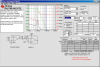
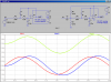
Here are two examples of LP filters; one that is running on split supplies, the other that is running on a single supply. Note that with split supplies, the input signal In1 can swing symmetrically around ground, and so does Out1. To run on a single supply, the input is biased half way between ground and Vdd by the two 470Ks. A coupling capacitor feeds the signal to the junction. The filter works the same, except its output Out2 is now centered at half Vdd.
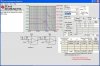
Note that the input coupling capacitor adds turns the filter into a band pass. Look at the second set of plots which are a Bode plot of Out1 and Out 2.
Sorry If This is a bit of topic,
My question is about dB:
I do know both voltage and power formulas explained by dB, But please tell me how to translate an attenuation of 15 or 20 dB for instance? an example would be very good to help me to understand this magically tool?!
An LM386 is not an opamp. It is a power amplifier complete circuit. It has built-in biasing and built-in negative feedback so it will not work in your opamp filter circuit.
An LM386 is not an opamp. It is a power amplifier complete circuit. It has built-in biasing and built-in negative feedback so it will not work in your opamp filter circuit.
Ok, thanks i replaced them with a opa2132 will that work? because i'm still having a gain problem but the filtter works if i give it lits of current but then my speaker distorts. could that be because i told the software to change the capacitors and now the resistors are too big?
ealso in the software it says you can change the capacitors but if you u enter one that is bigger then 1uf it says they are not supported but it puts some in that are 1u what is that? please help!!!
Ok, thanks i replaced them with a opa2132 will that work? because i'm still having a gain problem but the filter works if i give it lots of current but then my speaker distorts.
An OPA2132 is an opamp, not a power amp. It cannot drive a speaker.
Your opamps have no input bias voltage, no low impedance signal source and no power supply.
The filter circuit has a gain of 1 at very low frequencies.
An OPA2132 is an opamp, not a power amp. It cannot drive a speaker.
Your opamps have no input bias voltage, no low impedance signal source and no power supply.
The filter circuit has a gain of 1 at very low frequencies.
Another interesting idea is to make a third order filter from three passive filters tuned to the same frequency. The three passive filters however can not be exactly the same but should have a progressive impedance increase.
For example, the first stage might have a 1k resistor and 1uf capacitor, then the next stage would have a 10k resistor and 0.1uf capacitor, then the final stage would have a 100k resistor and a 0.01uf capacitor. In each stage the burden of the load of the next stage is reduced by a factor of 10 so that the overall response tunes like three stages of all the same values for all three stages isolated with voltage followers would tune in that the response is still very close to third order.
Of course in some cases this wont work because it will be difficult to obtain a low enough output impedance with a reasonably valued capacitor or reasonable impedance in the first stage, but it's still quite interesting at least. The good point is that it does not require an op amp.
A problem with a multiple-pole RC passive filter, besides any possible impedance problems, is that the corner rolloff is very soft. It will not have the sharp rolloff at the corner that an active or LC filter does.
Thanks, I know the formulas you mentioned, but I want to know how do you guys translate it, I mean, if you hear an attenuation of 15dB then do you start to think about How many input amplitude will lead to how many output amplitude? For instance do you interpret -15dB to 0.1778279 then multiple it to the (or any imaginary) input value to see how many amplitude you will get at the output?
I guess a real example would be very ok.
Ps. Are we able to tell that a given dB value is a COMMON value to compare to values, I.e it tell us the output value for different inputs, If you know what I mean??
This site uses cookies to help personalise content, tailor your experience and to keep you logged in if you register.
By continuing to use this site, you are consenting to our use of cookies.