Continue to Site

Welcome to our site!

Electro Tech is an online community (with over 170,000 members) who enjoy talking about and building electronic circuits, projects and gadgets. To participate you need to register. Registration is free. Click here to register now.

  • Welcome to our site! Electro Tech is an online community (with over 170,000 members) who enjoy talking about and building electronic circuits, projects and gadgets. To participate you need to register. Registration is free. Click here to register now.

3D printing - Anyone else on-board and if so, what printer do you have and what do you print?

Status
Not open for further replies.

Mickster

Well-Known Member
Most Helpful Member
I purchased a Geeetech Aluminium Prusa i3 a few months before Christmas 2017, mainly because I wanted to be able to produce a quick mock-up for any idea that I had regarding non off-the-shelf items that can be made, without spending a whole heap of time cutting/filing/welding/machining metal parts.
I have a couple of CNC machine projects currently in-progress and some other ideas, where I will likely need to make custom parts.
A 3D printer is perfect for this, as you can have a physical object in your hands in a few hours, that is produced virtually unattended.
As most people who start out with 3D printers do, I have been making upgrades for the machine itself and items on the Honeydo list, along with a few trinkets just to test out print quality etc.
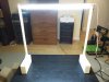
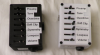
I'm currently only printing in PLA plastic, as I need to upgrade the PSU, add a MOSFET for the heated bed and build an enclosure, so I can print ABS without stinking out my workshop and/or causing any health concerns.
For part design, I am using Autodesk Fusion 360 and exporting the STL model to Repetier Host.
From Repetier Host, I am using Slic3r PE to produce the G-Code and printing parts solely off the SD card.

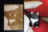
Our shower handle fell off (twice) when my wife was using it and no replacement part could be found locally.
An hour or so with Fusion 360 and about 4 hours printing produced the following, which has pleased her no end:
IMG_0892.jpg


IMG_0893.jpg
 
My brother is into it big time to the point he is running two machines near 24 hours a day several days a week or more.

He also does all his CAD work on Autodesk 360 which is free and does full 4+ axis CNC control.

I have no need for it being he can print me whatever I need in return for me doing metal fab work for him. Thats the extent of my knowledge.
 
I recently got myself a Tevo Tornado and I've been really loving it. While it doesn't have the extra fine 0.05mm resolution some smaller printers have, it has a good heated base as well as a very large 300x300x400mm print volume. Tevo printers also use special textured plastic sheets on their beds which have incredibly good adhesion for PLA.

I mainly got it to be able to easily print custom electronics cases for projects without having to drill holes or slots by hand, but I have found other uses for it as well. For example, on a whim, I played around with press-fit parts by making a set of weighted pedestals for an LED tube light to use as a bench light. I 3D printed holes in the bases of the pedestal into which I hammered pieces of scrap metal barstock to make the base heavier. I also downloaded files off of the net for a very slick-looking headphone stand.

I actually do my modeling in a somewhat roundabout way; I use simulation software at work called Ansys HFSS which has 3D modeling capabilities, so I actually model my parts up in that, then export the models as .step files into Creo Parametric to re-export as .STL files. I then use Repetier to generate the printer files, which I then load onto an SD card.
 

Attachments

  • IMG_1332.JPG
    IMG_1332.JPG
    1.2 MB · Views: 210
  • Untitled.png
    Untitled.png
    1.2 MB · Views: 199
  • unnamed.jpg
    unnamed.jpg
    56.4 KB · Views: 198
Last edited:
The labels in untitled.png look to be add-ons, but could they be made integral with the main print? Does Autodesk 360 have the ability to include text, either raised or indented?
 
Yes, they're just ordinary labels stuck on. Modeling raised or indented text in Autodesk is absolutely possible, but sadly I don't have that function in HFSS as far as I know. At some point I may want to learn a proper CAD program, but for the purposes of making quick mock-ups for prototypes it just happens to be something that is familiar and available to me.
 
The only issue I have with autodesk 360 is its 64 bit which makes it incompatible with any older 32 bit computers like what most of us would dedicate to running a DIY CNC system off of. :mad:
 
The labels in untitled.png look to be add-ons, but could they be made integral with the main print? Does Autodesk 360 have the ability to include text, either raised or indented?
Yes they can and it is probably very easy to do, although I have not done it yet.
You would create the text on a plane or face, in a 2D sketch, select all polygons required and then perform an extrude operation.
If the text was created on a face where you wanted the text, you could do a negative extrude and cut directly into that object, or a positive extrude to raise it. If the text was created on a plane, you could do a positive extrude and create a solid object, align it wherever you needed it to be on the other piece, then do a combine operation in which the intersection of the objects is a 'cut' operation. If you just wanted the text left raised, you would do a 'join' instead of 'cut'.
 
Played around in Fusion 360 for about 30 mins just now, to try the text out.
As described above, it really is that simple - I created a 100 mm cube and selected the right face, then used that surface to create a sketch.
Selected the text tool, inputted the required text, then dragged it into position. Repeated for the other 2 lines.
Performed a positive extrude on the text on that face, 'join' was the default setting, the text raised as expected.
Copied the text geometry from the sketch for the first face, selected the left face and created a new sketch.
Pasted the text geometry, moved it into position, selected it again but extruded in the negative direction.
'Cut' was automatically selected and the text was indented.
Exported the object to Repetier Host and aligned it on the print bed, to sit with the text facing horizontally.
Next step would be to slice the object for printing - the level of detail is dependent upon the print nozzle size and the layer height, as well as the material and machine capability.

Test.png


ETO.png
 
Why, when I look at the left face do I see an inside corner but the right side makes me see an outside corner? Anyone else?

Mike.
A trick of the brain? I had to look for a while to see what you describe, but the geometry is probably what is doing it.
If you look at the E and F especially, the diagonal angles of the lower horizontal parts do not make sense when viewed as you describe, but also barely make sense when viewed as it was modeled. That's probably due to a combination of the shallow depth of the cut and the angle which the render was created.
 
i got one of the "generic" printers (startt, which is a clone of the reprap), and have done a few things with it. i might try to fabricate some vintage radio knobs or guitar knobs and see if they are worth producing in quantity. my other idea was to get some of the rubbery filament and make custom grips for pistols.
 
Had another quick play with the text in Fusion 360, based on JLNY's boxes.
ETO box lids.png

Left side is indented text, 0.5mm below the surface. Right side is raised text, o.5mm above the surface.

Pics like this do not show enough detail, so if you are collaborating with someone on a project, F360 allows you to share.
You can restrict the share link to allow only viewing and measuring/sectioning/mark-up and snapshots, or you can allow the model to be downloaded in a number of different formats, as I have done here: (You can download the Fusion 360 archive)
http://a360.co/2pG83pi
The link opens a page on **broken link removed**

Regards.

EDIT: Just tried to download the file in one of the formats and you have to supply an email address to Autodesk for the download. This email address is not seen by me.
 
I got an engraver, had it a good while now, when we got it they were a huge amount of cash. The 3D printer Didnt last too long, Mach3 was the software I used for both and I cant remember the actual package now.

I have a decent set of small mills for the engraver but they were left in Devon by accident. I would like a laser cutter, but the tubes are still a bit under rated to be worth getting.
 
Laser cutters are something I have had an interest in, but I would agree that currently there aren't a lot of good options at the hobby level.

Earlier this year I bought one of the generic "K40 machine" laser engravers, but I haven't had enough time to do as much with it yet compared to my 3D printer. I can definitely attest that they are kind of a mixed bag to use. I understand folks say that the 40W laser tubes apparently do not necessarily meet their rated power, and while I'm not very knowledgeable about laser cutters, I find that they do a decent job on thin wood/acrylic.

That said, the quality of the construction in the units themselves is horrible -- and even rather unsafe. The supplied ventilation fan and cooling pump are janky as heck, the clamping mechanism on the bed is not very useful (and frequently comes damaged during shipping, as I found out), and I can say from experience that the lack of "air assist" on the lens causes it to get smoky, so it requires frequent cleaning to keep from overheating and cracking. Mine also had a bad grounding wire on one of the pass-through plugs for the pump/fan. Long term reliability of the laser tube is also a major concern and remains to be seen, as they are not cheap to replace.

In spite of all those issues, they seem to do reasonably well for what they are. Laser cutters are wonderfully precise, and once they have been fixed up a bit, the K40 units are decent for light-duty cutting as well as doing surface engraving. It seems like there are also a number of folks who perform mods or change out parts on their units to correct some of the design flaws with them. I myself have performed a couple after-market additions on mine to improve the ventilation and the cutting bed. So far I've done some semi-successful experiments with converting images to do surface engravings with, but my main plan is to start doing more with cutting parts to make more mechanical items and things like project cases with it.

Currently, my main issue is that I'm struggling to find good software to use with it. The unit comes packed with what appears to be a pirated license for an older version of a drawing program called Corel Draw, along with with their plugin for making it communicate with the laser. That said, I have had issues getting it to run on my operating system, and quite frankly I'm not overly fond of the idea of having to use pirated software to run my expensive laser engraver. Instead, I have opted to use a program called "K40 whisperer" to communicate with the laser and a free program called Inkscape to do my drawings.

Realistically, I would prefer to switch to a solution where I can export DXF cross-sections from a 3D CAD program rather than having to use Inkscape. (Once again, I knowingly shoot myself in the foot by trying to use HFSS as a modeling program, which on paper should have the capability to export DXFs from its models, but the functionality is buggy and generates additional geometry that has to be manually removed in order to be useful.) Does anyone know if Fusion 360 have the ability to export a cross-section of a 3D file as a .DXF? Perhaps that might be the solution I need for both of these.

I hope that in the future we will see a similar situation to 3D printers where laser cutters become cheaper and more accessible to hobbyists, but for now I would only recommend it to pretty dedicated hobbyists who have the space, resources, and patience to deal with the quirks of the units currently available.
 

Attachments

  • cel shaded test.jpg
    cel shaded test.jpg
    274.4 KB · Views: 184
  • Photo engraving test.jpg
    Photo engraving test.jpg
    248.1 KB · Views: 181
The trick with making the laser last is to not go above 50% power. Apparently the tubes are not rated correctly and get over driven, somewhere on you tube is an excellent series on a guy who did alot of work on the hobby level ones. I will see if i can find it.
 
Hi guys,
I have an Overlord Pro I got via their Kickstarter project.
It has a heated bed and I got the optional laser engraving add-on with it, though I have not used that yet.

It work well; it does not get a massive amount of use & a lot of the stuff I have done with it has been toys for a young relative; this is an example "make" from a design on Thingiverse:
https://www.thingiverse.com/make:144710

I've otherwise mostly used it for small parts, brackets, boxes etc.


If useful to others, the best software I have found for creating accurately-dimensioned models is the free Designspark Mechanical program from RS Components.
One of the first things I made using that program was a replacement battery door for a small device, complete with hairpin spring latches, working from vernier caliper measurements of the device it was to fit. The first one off the printer clicked straight in to place, which was quite impressive.

It's good program and I would strongly recommend it.

Link here: https://www.rs-online.com/designspark/mechanical-software
 
i use Octoprint for printer control, and Slic3r for code conversion. the best thing about Octoprint is that i don't have to have the printer connected to my main pc, and am using another machine as the print spooler.

i don't have a heated bed, so i'm using the "field expedient" of using a glue stick on the bed. it actually works ok.
 
Last edited:
Why, when I look at the left face do I see an inside corner but the right side makes me see an outside corner? Anyone else?

Mike.
it's an optical illusion, try looking at it with your room lighting on the opposite side of your monitor, and see if the effect reverses. the same thing happens when you look at pictures of craters (like on the moon).. if you shift your room lighting, your brain interprets the picture as craters, or as domes depending on which direction your room lighting is coming from. you can correct for it by rotating the picture until your brain interprets it as craters.
 
Printed_bits.jpg
I use Cura (the old 15.4.6 version) as the slicer and write the g-code files straight to an SD card; the Overlord has an SD slot built in so you don't need anything connected to run it.

I also use glue stick to give adhesion on the glass bed plate; it's what they recommend and does work well.

The photo shows a few example bits made with it that I have kicking about loose at the minute.
 
Last edited:
my "search-fu" failed me yesterday. a few days ago i saw a wire spreader for a multiturn loop antenna that goes in the end of a pvc pipe, it kind of looks like a "T" with wire spacers (like a comb) across the top, and a the upright section fits into the end of a PVC pipe. yesterday, i couldn't find it again, and i searched for several hours.

this is what you get when a search engine is written for "artists" rather than tech types... i put in [antenna] as the search term, and i get 500 results. if i put in [antenna wire spacer] i get 3000 results for everything from antenna, wire, and spacer, plus any and all combinations of those 3 words. since there were a lot of results from drone and FPV antennas, i tried [antenna wire spacer NOT"FPV" NOT"drone"] and got 10,000 results for everything containing any one or more of the words, including "not" (a lot of people misspell "knot").

i finally ended up downloading a wire spacer and a flat end cap for PVC pipe, printing them separately and gluing them together.

has anybody else had the same problem finding stuff after seeing it a few days earlier?
 
Status
Not open for further replies.

Latest threads

New Articles From Microcontroller Tips

Back
Top