Continue to Site

Welcome to our site!

Electro Tech is an online community (with over 170,000 members) who enjoy talking about and building electronic circuits, projects and gadgets. To participate you need to register. Registration is free. Click here to register now.

  • Welcome to our site! Electro Tech is an online community (with over 170,000 members) who enjoy talking about and building electronic circuits, projects and gadgets. To participate you need to register. Registration is free. Click here to register now.

3 Wire Load Cell question

Status
Not open for further replies.

MrSeaton

Member
Hi,

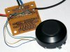
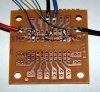
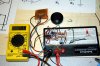
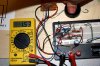
I'm messing around with some load cells I pulled out of a bathroom scale and I noticed that these load cells have only 3 wires unlike the 4 wire load cells I have been reading about. Does anyone have any information on these types of load cells and maybe what wires are for what?

Thanks
John
 
You have only 3 wires because it's a half bridge. Only 2 strain gauges present. It may be used with two fixed resistors to make a full bridge.
 
So if a wheatstone bridge consits of 4 resistors your saying that the 3 wire load cell takes the place of two of the resistors? And this is because it has two strain guages?

Going with that, How then do i connect the other two resistors and how do I find out what the resistance is of the strain guages? Without taking it appart how can I map out the wires?

I have a fluke 77III, can I use that to tell me what the resistance is and how do I translate the readout to a resistor I can buy at radio shack?

Thanks
John
 
Ok, That was a stupid post... A little reading and I got my answer.

for this explanation I will call the wires wire1 wire2 and wire3
When testing the load cell I noticed that touching wire1 and wire2 gave me a reading and then touching wire2 and wire3 gave me the same reading but touching wire1 and wire3 gave me a reading twice the that of the first two radings.

This gave me an idea. I knew I had some resistors laying around so I found 2 that were the same and I tested each individually and then I twisted two of the ends of the resistors together and measured them from the two untwisted ends and it gave me the same result, twice the resistance. Ok, that makes sense.

Now I just have to figure out this diagram I found on a site and see if I can picture this perticular setup. I'll modify the image and post it here to see if I'm right.
 
The individual rsistances were probably close to 350 ohms. If you use two fixed resistors to complete the bridge, matching the resistors closely is more important than them being exactly 350 ohms. Anything from 360 ohms up to 1000 will probably do fine. Check the Omega Engineering site for info on strain gauges and arrangements of them.
 
Ok, here are the two images
 

Attachments

  • Wheatstone Quarter bridge Circut.gif
    Wheatstone Quarter bridge Circut.gif
    2.3 KB · Views: 8,073
  • Wheatstone Quarter bridge Circut modified.GIF
    Wheatstone Quarter bridge Circut modified.GIF
    3.3 KB · Views: 7,577
  • Wheatstone Quarter bridge Circut With Pos and Neg.GIF
    Wheatstone Quarter bridge Circut With Pos and Neg.GIF
    3.4 KB · Views: 9,865
Last edited:
Ok, here is the image I found on the internet.
wheatstone-quarter-bridge-circut-gif.14488


Here is the one that I modified to what I think I will have when I complete the circut with the other two resistors.
wheatstone-quarter-bridge-circut-modified-gif.14489


Ok, I think I need to make one more image to clerify things a bit and then I think I've got it.

Thanks
john
 
Ok, here is the other image.
wheatstone-quarter-bridge-circut-with-pos-and-neg-gif.14490


Thanks for letting me know that they didn't have to be exact. That was another question I had. you must have read my mind.

Off to go do some more reading and some more testing...
 
Ok, I found the correct configuration for a half bridge circuit. I modified my image I found to show the correct configuration.
 

Attachments

  • Wheatstone Half bridge Circut.GIF
    Wheatstone Half bridge Circut.GIF
    3.3 KB · Views: 5,261
I made the circuit and it works. The only thing is that the output is in millivolts. I will have to build an amplifier circuit to be able to bring the voltage up to 2.5 - 5v. I'll post more on that later.

Here are the pics of the design so far.
 

Attachments

  • Load Cell and Circuit.jpg
    Load Cell and Circuit.jpg
    440.9 KB · Views: 2,030
  • Load Cell Circuit.jpg
    Load Cell Circuit.jpg
    646.5 KB · Views: 1,952
Nice pics, in focus too, makes a nice change from some of the recent pics on here.

To amplify your bridge output, it would be easiest if you use an op-amp, a 741 if you have one, but they are a bit of an old design, a TL072 would probably be better.

If you moved your bridge completion resistors to one end of the board, there would be room to mount the op-amp and associated components.

JimB
 
Thanks for the kind words on the pics.

I'll do some looking around and see if I can find some info on the TL072 and a diagram on building the circuit.

Thanks again for the info.
 
Well, I went to radioshack today and got some parts for my amp. I ended up using LM324 Quad Op Amp and I built a 3 Op Amp Instrumentation Amplifier.

I've got it on the bread board for right now just to make sure I could get it to work. To my surprise it works like a champ. I'll attach some pics of what I've got so far.

My next step is to design a pcb board and maybe try my hand at etching one out. I should be able to make one nice and compact that way.

Anyway here are the pics.
 

Attachments

  • Load Cell and Amp.jpg
    Load Cell and Amp.jpg
    809.7 KB · Views: 2,821
  • Load Cell and Amp With Load.jpg
    Load Cell and Amp With Load.jpg
    855.9 KB · Views: 2,038
Does your instrumentation amp have provisions for zero & span adjustments for calibration trimming purposes? Typical if you increase the gain resistor to more then you normally need then connect a 10 or 20 turn trimmer pot to the output of the amp to ground and take your measurement output from the pot's wiper. Zero adjustment is usually a trimmable voltage reference feeding the input to the amp.

Not sure of the weight range of your cell but several years ago I build a 0-5 gram scale using a very small Omega Co. strain gage. I used new US quarters as my validation weights. I forget what a quarter weighs but they are pretty tight tolerence and simple to validate and calibrate with.

PS a Tare function is also very useful but that is more easily done in the measurement system then in the sensor circuit.

Good luck
 
Status
Not open for further replies.

Latest threads

New Articles From Microcontroller Tips

Back
Top