Continue to Site

Welcome to our site!

Electro Tech is an online community (with over 170,000 members) who enjoy talking about and building electronic circuits, projects and gadgets. To participate you need to register. Registration is free. Click here to register now.

  • Welcome to our site! Electro Tech is an online community (with over 170,000 members) who enjoy talking about and building electronic circuits, projects and gadgets. To participate you need to register. Registration is free. Click here to register now.

3 Wire Load Cell question

Status
Not open for further replies.
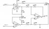
The only adjustment I have is on the gain. I put a 15 turn pot in the place of the gain resistor and adjusted it untill I got 1 volt. I have no idea if that is wrong but it appears to be working just fine.

I'll do some looking into the zero and span adjustments. That sounds neet and I could see the need for it.

Thanks
John
 
Here is the schematic for what I have minus the cap (I was told I didn't need it). Can anyone tell me if I have the pot wired wrong? It seems to do the job I wanted it to do but for some reason not having part of it wired just doesn't look right.

Thanks
John
 

Attachments

  • Instrumentation Amp Schematic.jpg
    Instrumentation Amp Schematic.jpg
    71.4 KB · Views: 7,602
MrSeaton said:
Here is the schematic for what I have minus the cap (I was told I didn't need it). Can anyone tell me if I have the pot wired wrong? It seems to do the job I wanted it to do but for some reason not having part of it wired just doesn't look right.

Thanks
John

It's correct. Wired as a two wire device it would be called a variable resistor (just two terminals required). When using all three leads, then it's used as a potentiometer (requiring 3 terminals).

Lefty
 
Ok,

I've been playing around with the span and zero options but in the mean time I'm going to make a board with the setup I have now.

I downloaded the free expressPCB software and played around with some designs. The first one was way to compact so I streached it out a bit and I came up with something I like and I think I can work with a little bit easier.

Here is the picture of the design from the software.
 

Attachments

  • PCB Layout.jpg
    PCB Layout.jpg
    61.2 KB · Views: 643
I've also been working on making that design into a board. So I found a process that works good using a laser printer and some paper I bought from a local office supply store.

Here is the process I used.
1. Use Steel wool #000 to clean the board.
2. Print the circuit design on a laser printer using office Depot Premium gloss presentation paper. (it worked good for me)
3. Tape the design onto the board. (I used Scotch magic tape, the semi-clear stuff)
4. Use a cloths iron to apply heat to the board to transfer the laser printed image. I set my iron on high and pressed hard for 3 minutes.
5. Let the board cool.
6. Mix up a batch of warm soapy water and place the board in the solution for about 20 minutes.
7. when the paper is fully soaked rub the paper off and then use your fingernail (lightly) to scrape off the paper from around the lines and inside the holes.

When your done it should look someting like this.

Next i'm working on etching it. I'll post some pics when I'm done with that too.
 

Attachments

  • PrintedPCB.jpg
    PrintedPCB.jpg
    275.9 KB · Views: 408
I finished the board tonight and I'm posting pictures of the board.
 

Attachments

  • EtchedPCB.jpg
    EtchedPCB.jpg
    187.7 KB · Views: 394
  • EtchedAndCleanedPCB.jpg
    EtchedAndCleanedPCB.jpg
    156.5 KB · Views: 416
Well, Its all finished and wired up and some how it works.

Here are some more pics of the completed board.
 

Attachments

  • CompletedAmp.jpg
    CompletedAmp.jpg
    186.1 KB · Views: 524
  • CompletedAmpHookedUptoVoltmeter.jpg
    CompletedAmpHookedUptoVoltmeter.jpg
    441.1 KB · Views: 644
So the next step is to make an analog to digital converter to process the analog voltage and send it to the computer.

I found a project from Parallax.com for their homework board (just happen to have one of those) on how to make a digital volt meter using an ADC0831 chip. I did some searching around and Digi-Key had them for less than $3.00.

When they get here I'll be building the A/D conversion circuit and testing. As always I'll post some pictures when I get it working.

John
 
It's probably cheaper, easier, and higher performance, to use a PIC to do the A2D, it will also do a serial connection to the PC as well. Something like a 12F675 is an 8 pin single chip solution, and gives 10 bit resolution rather than 8 bit.
 
Thank you for that bit of info. Sounds cool, I'll do some searching around and see what info I can find on it. You can't beat "cheaper, easier, and higher performance"

Thanks
John
 
hi John,

Been looking thru the threads on this post, I would like to say the way you have developed and presented each stage on this project IMO is excellent.

Well done.:)
 
MrSeaton said:
Thank you for that bit of info. Sounds cool, I'll do some searching around and see what info I can find on it. You can't beat "cheaper, easier, and higher performance"

My tutorials already have all the code required, although it's for the 28 pin 16F876 - but it's easily ported to the 8 pin 12F675.
 
ericgibbs said:
hi John,

Been looking thru the threads on this post, I would like to say the way you have developed and presented each stage on this project IMO is excellent.

Well done.:)


Thank you for the kind words. It has been an awesome learning experiance for me and alot of fun too.

John
 
Nigel Goodwin said:
My tutorials already have all the code required, although it's for the 28 pin 16F876 - but it's easily ported to the 8 pin 12F675.


Cool, I'll have a look through your site for it then.

THanks
John
 
Fantastic

I see this thread is a few years old, but I just wanted to say this is a great write up. I dissected a bathroom scale last night and had a 3 wire load cell that I couldn't figure out what to do with. Thanks again and great job
 
Hey there,
I'm having the same problem with some load cells I found in a bathroom scale, In this image is R1 a resistor with the same resistance of the strain gauge or it is the strain gauge in two parts?
QUOTE=MrSeaton;245604]Ok, here is the other image.
wheatstone-quarter-bridge-circut-with-pos-and-neg-gif.14490


Thanks for letting me know that they didn't have to be exact. That was another question I had. you must have read my mind.

Off to go do some more reading and some more testing...[/QUOTE]
 
Status
Not open for further replies.

Latest threads

New Articles From Microcontroller Tips

Back
Top