Continue to Site

Welcome to our site!

Electro Tech is an online community (with over 170,000 members) who enjoy talking about and building electronic circuits, projects and gadgets. To participate you need to register. Registration is free. Click here to register now.

  • Welcome to our site! Electro Tech is an online community (with over 170,000 members) who enjoy talking about and building electronic circuits, projects and gadgets. To participate you need to register. Registration is free. Click here to register now.

3 tx's, 3 results.

Status
Not open for further replies.

mstechca

New Member
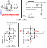
Take a look at these transmitters. I have built each one of them and the results are shown in the attachment. The middle one seems to work the best if the RESET pin of the 7555 is tied high.

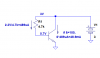
BUT, I want to make a transmitter that can transmit a tone, just by making something positive or negative. And it looks simple with the 555, but it is more complex.

What I want to do is take the output from a 555 timer, and drive it into a transmitter, and produce a long range transmission. I hope to have over 60 feet.

My other design I published on here works fine, but it is not compatible with my receiver. In other words, if I used the exact same capacitors for tuning in both the transmitter and receiver, the published design will not work with them.

Please help.

and I'm not joking here!
 

Attachments

  • 3fmtx.gif
    3fmtx.gif
    8.5 KB · Views: 582
  • 7555ext.gif
    7555ext.gif
    2.4 KB · Views: 587
You don't have the Cmos 555 oscillator wired correctly.
Your FM transmitter's transistor has such a high base current that the transistor is always saturated.
Supply bypass capacitors are missing.
 

Attachments

  • mstechca.png
    mstechca.png
    20.2 KB · Views: 587
Well, you can't saturate a transistor that has no current limiting resistors in the collector-emitter circuit, but you can draw a lot of current! With a 4.7k base resistor, a 3 volt supply, and a beta of 100, collector current will be about 50 ma. This is the absolute maximum collector current for this part.
Also, Ft is spec'ed at Vce=10V and Ic=8ma, Which is probably the optimum point. It will probably be less than that for any other combination of voltage and current.
 
You know what, I drew the 555 circuit wrong. I was thinking too fast. I meant to direct connect pin 2 to pin 6 and connect a capacitor between pins 2 and 1.

Sorry, but I like to get things done (too) quickly.
 
Ron H said:
Well, you can't saturate a transistor that has no current limiting resistors in the collector-emitter circuit, but you can draw a lot of current! With a 4.7k base resistor, a 3 volt supply, and a beta of 100, collector current will be about 50 ma. This is the absolute maximum collector current for this part.
Also, Ft is spec'ed at Vce=10V and Ic=8ma, Which is probably the optimum point. It will probably be less than that for any other combination of voltage and current.

I guess that means my long-range circuit (in the middle) is almost always under saturation. The audio is connected to the collector of the NPN.

I can't connect the audio output to the NPN's base because 1) I'm asking for inversion, 2) It will jeopardize the frequency of the transmitter portion set by the 330pF capacitor and the 4.7K resistor, and 3) the gain is lower.

I'm ok with heavy saturation, because I want the signal to get through. As I said, it works great when the reset pin is connected to +ve. When the reset pin is connected to -ve, it doesn't work. Sometimes, the wrong audio tone is emitted!

Also, I am using 47uF battery coupling capacitors, and it even does not make a difference.
 
mstechca said:
I guess that means my long-range circuit (in the middle) is almost always under saturation. The audio is connected to the collector of the NPN.

They all use the same value bias resistor, so all will be passing too much current and not working properly (not helped by replacing the emitter resistor by an inductor - for some bizarre reason?).

I can't connect the audio output to the NPN's base because
1) I'm asking for inversion,

What difference does that make?.

2) It will jeopardize the frequency of the transmitter portion set by the 330pF capacitor and the 4.7K resistor, and

Neither of those components set the frequency - you still appear to have no clue how it works?. I'm sure we've told you before?, but the 4.7K is the base bias resistor (and too low), and the 330pF grounds the base at high frequencies to allow the transistor to operate in common-base.

3) the gain is lower.

No gain involved, it's an oscillator - it either has enough gain to provide oscillation, or it doesn't work!.
 
mstechca said:
I'm ok with heavy saturation, because I want the signal to get through.
The transistor has too much base current because the value of the base resistor is too low, therefore the transistor doesn't work properly.
Haven't you tried increasing the value of the resistor?

As I said, it works great when the reset pin is connected to +ve. When the reset pin is connected to -ve, it doesn't work. Sometimes, the wrong audio tone is emitted!
A 555 oscillator oscillates when its reset pin is at +ve. It is reset and won't oscillate when its reset pin is at ground.
The tone level from the 555 is extremely high, it needs an attenuator.
The impedance of the output of the 555 is very low and is severely loading-down the RF section of the transmitter. An attenuator will also help reduce the loading.

I am using 47uF battery coupling capacitors, and it even does not make a difference.
A 47uF electrolytic capacitor is an inductor at radio frequencies. It is fine for audio but a 330pF to 2000pF ceramic disc cap is an RF supply bypass.
 
Mstechca, just so we are all on the same page, saturation in a BJT is defined as having the collector-base junction forward-biased. As I said, your transistor is not saturated. It's just drawing too much current, and you have no feedback to control the bias point. A resistor between emitter and ground will provide negative feedback. If you insist on having an inductor in the emitter circuit, you still can - in series with a resistor. You can bypass the resistor with a cap if you think it upsets your RF performance.
I'm not going to offer any RF advice, because previous attempts have proven futile. :roll:
 
What difference does that make?.
If I use inversion, doesn't that mean I need to remove the coupling capacitor between the audio stage (the 555 circuit), and the transmitter stage (the circuit in yellow)?

In a 2-stage common emitter amplifier using 2 NPN's, output is seen at the collector, and a capacitor is connected between the NPN's collector and the 2nd NPN's base. I see that the output goes from the "N" connector of one transistor to the "P" connector of the other transistor, and a capacitor stores a voltage when opposite polarities touch both pins of it. If I made the first NPN, a PNP, I can't see how a capacitor will logically fit, and therefore, if a direct connection was used, more current will be used.

My point is that I need to capacitor couple my signal to effectively isolate (in DC mode) the audio stage from the transmitter so that the signal can pass through.

Haven't you tried increasing the value of the resistor?
I have tried 9.1K but the range is much lower, and the circuit just about doesn't work when the battery drains to about 1.5V from 3V.

A 47uF electrolytic capacitor is an inductor at radio frequencies. It is fine for audio but a 330pF to 2000pF ceramic disc cap is an RF supply bypass.
maybe that is my problem.

Neither of those components set the frequency - you still appear to have no clue how it works?. I'm sure we've told you before?, but the 4.7K is the base bias resistor (and too low), and the 330pF grounds the base at high frequencies to allow the transistor to operate in common-base.
Someone (I think Audioguru) mentioned that such a configuration creates a low-pass filter. I'll take your word. I suppose I should calculate Xc of the capacitor and make the answer as close to 0 as possible with my frequency.

With a 4.7k base resistor, a 3 volt supply, and a beta of 100, collector current will be about 50 ma. This is the absolute maximum collector current for this part.
I don't understand how you got about 50ma. According to my calculator,

3V / 4700 ohms = 0.000638298 amps
which is 638uA, going from +ve to NPN's base.
It is the NPN's base which turns on the transistor.

(not helped by replacing the emitter resistor by an inductor - for some bizarre reason?).
My emitter is connected to a tuned circuit. I use "gang-tuning".

I wonder, do transistors act strange if too much current enters the collector pin of the NPN and no current enters the base?
 
I don't understand how you got about 50ma. According to my calculator,

3V / 4700 ohms = 0.000638298 amps
which is 638uA, going from +ve to NPN's base.
It is the NPN's base which turns on the transistor.
For now, I'm just gonna address the BJT current issue. The little schematic below should explain it. This is not a simulation. If the beta is not 100, the collector current will be different, as shown by the equation.
 

Attachments

  • bias.png
    bias.png
    6.6 KB · Views: 504
The little schematic below should explain it. This is not a simulation. If the beta is not 100, the collector current will be different, as shown by the equation.
Between yesterday, and today, I kind of figured it out. Thanks for clarifying it.

Ron H said:
It's just drawing too much current
I upped my resistor to 6.2K which makes the collector current a few mA short of the maximum limit. The PN3563 accepts a 50mA maximum safely.

...and you have no feedback to control the bias point.


It seems that my transistor configuration is common base. The capacitor connected between base and ground is acceptable if it is high enough (300pF+). This sends the reactance down to a fraction of an ohm, making the base literally grounded at VHF.

Now let's look at the two inductors. Wouldn't you think that with higher frequencies, their reactances go up? Couldn't I think of them as Let's say 5 - 10 ohm resistors a piece?

AND check this site out:

it states that current flows from the emitter, through the base, and into the collector. I want to emit a voltage, because a good amount of current is already coming out of the 555's output pin. and if current * voltage = power, hey, all the better! POWER IS GOOD! :lol:

Also, the site states:
Since it obviously can't boost signal current, it only seems reasonable to expect it to boost signal voltage.

Maybe it is my resistor AGAIN. I didn't take tolerances into account.

A resistor between emitter and ground will provide negative feedback.
My inductor in DC mode is a very low-value resistor, and in AC mode at VHF, it probably is a bit higher. A resistor, if high enough can make performance suffer.

If you insist on having an inductor in the emitter circuit, you still can - in series with a resistor.
I have a question. Why a resistor instead? They limit more current.


I'm not going to offer any RF advice, because previous attempts have proven futile. :roll:
The resistor advice has. I want to avoid current limiting, unless I have to. and in the case of the collector to base resistor, I have no choice, or my transistor will be flying so high, it might hit Audioguru's window :shock: :lol: j/k.

Hey Audioguru, Did you see alot of smoke of mine coming your way (10 years ago when I just started in electronics)? :lol:
 
High current in a transistor that is caused by having the base-bias resistor's value way too low, and without having an emitter resistor to "regulate" the current causes heat, not output power. It also wastes a lot of battery current.

The 555 has a high output current when it feeds a low resistance load. Your circuit has the 555 driving the dead shorts of high frequency inductors, except when it drives the base.
The output voltage of the 555 is way too high for your circuit and the very low output impedance of the 555's output loads-down your circuit so much that it can't function.
 
audioguru said:
High current in a transistor that is caused by having the base-bias resistor's value way too low, and without having an emitter resistor to "regulate" the current causes heat, not output power. It also wastes a lot of battery current.
I don't feel any heat. I can agree that a lot of current is used, and it is intentional, because that can make the transmitter operate better, but of course, too much current is bad.

Doesn't the resistor connected to the base help limit the current from emitter to collector, or does a transistor function as a latch so that when so much current or voltage is received at the base, the latch is enabled and maximum current flows from emitter to collector?

I always thought the resistor connected to base has an effect on the entire current consumption.

The 555 has a high output current when it feeds a low resistance load. Your circuit has the 555 driving the dead shorts of high frequency inductors, except when it drives the base.
That is still true even if I have capacitor coupling? (capacitor between 7555's pin 3, and emitter)

The output voltage of the 555 is way too high for your circuit and the very low output impedance of the 555's output loads-down your circuit so much that it can't function.

How do I calculate the optimal voltage?
I wonder if that is why I hear a random noise instead of dead air when RESET pin is low.

I learned that current flows from emitter to collector in a common-base amplifier. If I replaced the inductor with a resistor, I will reduce current consumption, and therefore range will be reduced.
 
mstechca said:
don't feel any heat. I can agree that a lot of current is used
50mA times 3V is 150mW. The battery also warms a little. The 555 that is driving a short warms a little. A huge waste of battery power.

Doesn't the resistor connected to the base help limit the current from emitter to collector, or does a transistor function as a latch so that when so much current or voltage is received at the base, the latch is enabled and maximum current flows from emitter to collector?
No. A transistor is linear. An increase of base current results in an increase of emitter-collector current. Your base resistor's value is too low resulting in too much base current and too much emitter-collector current.

I always thought the resistor connected to base has an effect on the entire current consumption.
It does. If its value is higher then the current is lower.

That is still true even if I have capacitor coupling? (capacitor between 7555's pin 3, and emitter)
Calculate the very low reactance of the capacitor at the 555's frequency.

How do I calculate the optimal voltage?
You calculate the effect of the modulating voltage on the current of the oscillator. When the modulating voltage and current are too high then the oscillator is cutoff during parts of the modulation and has its average frequency changed.

I wonder if that is why I hear a random noise instead of dead air when RESET pin is low.
I think the RF frequency is changed because the modulation is much too strong.

I learned that current flows from emitter to collector in a common-base amplifier. If I replaced the inductor with a resistor, I will reduce current consumption, and therefore range will be reduced.
The transistor needs to be biased to a proper amount of current so that it can have a high output voltage swing. It can't if it is conducting too much.
 
The first time someone mentioned that the current feeding the base was too much, I changed the resistor to 6.2K. According to Ron's equation, multiplying the base current by the assumed HfE of 100 will result in 48mA for collector current, which is within limits because the transistor accepts a 50mA maximum current.

if I were to add a resistor at the emitter or the collector, what is the lowest value you recommend I should use?
I prefer having it at the collector. (by replacing the inductor with an inductor and a resistor in series).
 
A resistor is connected from the transistor's emitter to ground as negative feedback to iron-out the huge difference in current gain of transistors.

If the transistor's gain is low, then less voltage is developed across the emitter resistor so its base and emitter-collector currents are increased. If the transistor's gain is high then more voltage is developed across the emitter resistor so its base and emitter-collector currents are decreased.

Most little transmitters use a 220 ohm emitter resistor but 100 ohms would have less loss.

My transmitter uses a 2N3904 transistor with a typical current gain of 220, and uses a regulated 5.0V supply. Its average oscillator current is 8.8mA.
 

Attachments

  • fm_oscillator.gif
    fm_oscillator.gif
    2.9 KB · Views: 427
That represents a variation of one of the most advertised transmitters available for anyome to build.

I do have some problems with it.

#1. I cannot get exceptional range like I can with mine.

#2. Most transmitters that are available to build insist that the antenna should be used at the collector. The problem is that it functions as a nearby hand detector instead of a decent transmitter. (it changes frequency when the antenna is close to being touched by your fingers)

#3. the 220 ohm resistor is a big problem to me. When I started with transmitters, I used the design you showed, and nothing came close to my recent design in terms of transmitter range.

Basically, the only BIG difference between your posted design and mine is that the emitter and collector pins are swapped, and input is injected into the collector.

I still think it makes sense that voltage flows from the collector to the emitter if current flows from emitter to collector in a common base amplifier. am I right, or do I need to take more common-base amplifier lessons?


A resistor is connected from the transistor's emitter to ground as negative feedback.
and since negative feedback is degeneration, and since it can reduce gain, I think it is best to avoid it as much as possible. If a resistor is 100% necessary, then maybe an ohm or two is about it.

If the transistor's gain is low, then less voltage is developed across the emitter resistor so its base and emitter-collector currents are increased. If the transistor's gain is high then more voltage is developed across the emitter resistor so its base and emitter-collector currents are decreased.
Doesn't the base resistor and/or the inductor connected to the collector limit the voltage to an extent?

Also, I have a tank circuit connected between emitter and ground. Isn't it true that the reactance of the tank is high at the resonant frequency?
 
A transistor circuit needs to be biased at the proper operating point which depends on its load impedance and its supply voltage. Your circuit is operating at a very high DC current so it can't possibly have much voltage and current swing in the load (power in the antenna) for much range.
 
Disclaimer: I don't recommend this, but...
if you want to individually adjust the collector current of your transmitters, you can do it by tweaking the base bias resistor of each one while monitoring the collector current with a multimeter. The current will vary somewhat with temperature (it will go up as the temperature goes up), but probably not to the point of destruction, if you start with a reasonable current level. Be aware though, that it is a thermal positive feedback situation, i.e., temperature goes up therefore current goes up therefore temperature goes up therefore....
A much better solution from several aspects would be a low-power FM oscillator followed by a class C amplifier. The class C stage can run directly off the supply rails without worrying about needing negative feedback to solve the above-mentioned problems. The class C stage also eliminates most of the incidental AM that you get from the oscillator/modulator, which you will also get from your one-transistor hardhead transmitter.
As a side note, I think there is an optimum current for a given supply voltage that will give you maximum output power. Raise the current beyond that, and you are just discharging your battery and heating your room. The optimum current will, I think, depend on antenna impedance, among other things, and I don't know how to calculate that, mostly because I don't know much about antennas.
 
MStechca's transmitter has its tank as its emitter to ground resistor. Therefore the antenna can't have a voltage swing that is much higher than the supply voltage which results in a high RF power output as occurs when the antenna is connected to the transistor's collector.

Also, the tank is trying to be a high impedance parallel-tuned circuit, but it is in a low impedance emitter circuit so the frequency stability of the oscillator is probably very poor.
 
Status
Not open for further replies.

Latest threads

New Articles From Microcontroller Tips

Back
Top