maknelly90
New Member
Hey guys, I am currently designing a 3 stage BJT amplifier with a 3V DC source. I am using 20mV as my input and I want a gain of -20V/V. However, I have a limitation of 50k ohms as my input impedance. In my completed circuit, I currently have a gain of -3 with a slightly larger positive gain than negative gain but I meet the imput impedance requirements.
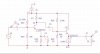
In my second schematic, I have completed stage 2 and 3 of the amplifier. Stage 3 is my buffer stage. I am looking for a gain of -5 n my second stage to reach my goal of -20. I have chosen my gain for the first stage to be -4 so that the second stage for my gain is -5. If I simulate this schematic, I get a 400mVpk with an input of 80mVpk which is exactly what I need. However, my input impedance will be lowered because of the small resistance in the emitter of the 2nd stage.
Do you guys have any advice for me of achieving a -20V/V gain while having an input impedance in the first stage of 50k ohms?