Continue to Site

Welcome to our site!

Electro Tech is an online community (with over 170,000 members) who enjoy talking about and building electronic circuits, projects and gadgets. To participate you need to register. Registration is free. Click here to register now.

  • Welcome to our site! Electro Tech is an online community (with over 170,000 members) who enjoy talking about and building electronic circuits, projects and gadgets. To participate you need to register. Registration is free. Click here to register now.

3 aspect model RR signalling help plse

Status
Not open for further replies.

angie1199

New Member
Hi all,

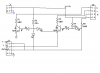
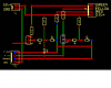
I've followed the circuit here **broken link removed** and came up with this layout on my breadboard **broken link removed**

Tested three blocks in a loop with green in going to ground to enable green as default on all blocks. All worked.

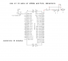
Built single block on stripboard and tested as single block.

Green light is on by default, so far so good.

When yellow out is put to ground red led comes on but green just goes dim. Likewise when yellow in is put to ground yellow led lights and green goes dim.

On both occasions green should go out.

Any ideas why the stripboard fails were the breadboard works? I've checked for shorts across the tracks and track breaks are fully broken. I have already built this circuit once and it did the same, and after removing all the components they were still all working correctly.

Starting to pull my hair out atm so any ideas would be helpful at this time.
 
Last edited:
Further to this, if I touch Q1 the green led get's brighter. As I have no idea about components, only how to follow a schematic, is this usual, i.e. is my finger acting as an antenae for the transistor and getting a signal from the D1 diode?

In which case, is the transistor too close to the diode?
 
read further down about adding more diodes.
this circuit looks very convulated (not right) and could be made simpler.
just the labeling of track block detectors as outputs makes ,me wonder about the designer??
let me build in LT Spice and will get back to you with better circuit hopfully.
I just need to understand what this circuit is doing??
 
got it working in Multisim

only 1 1/2 blocks (can't add any more, stupid program. I don't like using it but LT sice dosn't have switches).
I found the circuit works better using 500-600 ohm resistors instead of the 1K resistors.
going to try and simulate in TINA (I like seeing the little leds light up)
got to be a better circuit?
 
read further down about adding more diodes.

Appreciate your time on this MrDeb. I read the notes about additional diodes but it says that's when it's being switched by a block detector which is the next item on my build agenda once I have this signal changing system sorted.

At present I'm just using a switch which, on the two blocks on the breadboard work perfectly. This is why I'm confused. If it works on the breadboard why doesn't it work on the stripboard.

(edit)
Also, as you say, I have used 560R resistors instead of 1K the 1K resistors
(end edit)
 
Last edited:
I would double check your circuit board using a DVM.
disconnect the power and using ohms check ALL your solder connections.
then recheck voltages hat should be expected.
got to be a bad connection seeing how led gets brighter when touching transistor.
double check transistor polarities as well.
 
I think your missing grounds

here is a strip board layout that might help.
I used basically same layout but added additional connectors.
see schematic.
green are jumper wires and red are the strip board traces
hopfully this solves the problem?
 

Attachments

  • train block.PNG
    train block.PNG
    29.3 KB · Views: 445
  • train blk.PNG
    train blk.PNG
    30.9 KB · Views: 429
WELL did you get this circuit working??
lots of posters help but very little feed back on results.
 
As you said, 'checkyour circuit board' :)

I have no idea what readings I should get, and where I should get them, but I did check all components and all were working. I re-soldered each joint to the transistor that was causing the led to glow brighter when touched and that has made the green now go out when yellow or red are lit.

Another issue has materialised now. It may have been there before but due to the more immediate problem I never noticed it. Now, if block 2 is red then this block goes yellow, not a problem. However if this block then goes red at the same time, the yellow should go out and the red come on but this is not happening, the yellow and red now share power when this situation occurs.

I've ensured there's no shorts across tracks and the problem still occurs. LEDs are now fixed brightness. Could this be Q2 as the problem, is this the behaviour of a blown transistor even though it does appear ok?
 
did you use a heat sink when soldering transistors?
if not then you very well may have cooked a transistor.
how many blocks are you wanting?
I could design and etch a pcb for you if you want. may make things easier?
just pay for shipping. no big deal.
 
I built circuit in simulation program TINA (free down load)
It works fine.
It sounds lke your circuit is working right (see schematic of 5 blocks in link you posted)
should be 0, yellow, red, red, green
if you download TINA I can email you file then just probe with DVM
real easy and very graphic.
 
Not sure how many blocks I'll need just yet, somewhere near 20 I think.

I'll take out Q2 and use it to replace one on the breadboard to see if it's ok. If the breadboard circuit works then I know it's not the tranny.

I've got TINA installed but keep getting an error saying circuit is too big! It's only a small circuit.
 
you need to have a TI componet on same screen

I have had that happen.
I have 3 blocks and it works but I am not real happy with the circuit design.
my so called concerns
feel that ALL the green LEDs should be lit until train enters block A
block-A = red on, BLK-B yellow on
BLK C>X all green
have yellow on one blk before blk that train is in
train going from A to F
A=red, B=yellow, C>F= green
train in blk C
A=green, B=yellow, C=red, D=yellow, E>F green
Then add a flashing LED for train approaching.
train in blk C
A=green, B=yellow, C= red, D=flashing yellow, E>F=green
flashing indicates approaching train.
not sure if this is in real life but??
am very interested in the operation of this simple circuit BUT it needs improvement.I used to run N gauge as well as HO years ago.
simed using D flip flops, thinking or gates even a PIC
now a PIC you could really do something.
perhaps even automatically throw turn out switches so trains can't collide head on. Add flashing LEDs etc.
 
I'm modelling N gauge and there are two mainlines, up and down, so no need for caution to be given ahead of block.

In sidings a two aspect signal will be wired in to the junction or junctions ahead and then a signal at last junction indicating if block ahead is clear etc.

I need to build each block as a single unit as each will be located nearto their own blocks otherwise there would need to be miles of wiring. The model will have a power bus for 12v specifically for the signalling. the yellow in and out will go to the next and previous blocks so not too long a wire, and the block detector circuit will be next to the block it monitors.

With my 'very' basic knowledge of electronics I chose this circuit over others on the website as it covers the prototypical operation of signalling where the model is modelled on. Some signalling has flashing yellow(s) but the scenario I'm modelling doesn't require it.

What I have discovered through your assistance is that my soldering is 'rubbish'. I'm wondering if I'm using a wrong iron. I have a weller 25W with pointed tips which I'm using, but I also have a 15W Weller which I'd have to get new tips as the one in it is burnt out, but it's smaller. Your thoughts on this would be most welcome.
 
Have a PIC designed circuit

no transistors, a lot fewer parts and only two wires from controller to each set of LEDs
using cat5 cable you only need one cable to each block.
CAT5 is cheap and could use RJ 45 plugs to make wiring easier.
circuit description
train in blk F
ALL GREEN LEDs on except BLK F
RED LED on BLK F and YELLOW LED on BLK G
one 18F452 can control 14 blocks
very easy program, I or some one else on this form can program. Just pay for shipping and PIC. If you want, get 2 pics free from microchip as samples.
Pic is under $5
PCBoard, I can etch as well. just pay for shipping.
soldering= are you using small diameter rosin core solder?
I found lightly sanding board before soldering with 400 wet dry sandpaper. Dry using paper towel, Alcohol helps as well.
Also procure a tub of rosin soldering flux. Dip tip of solder into flux then apply heat to board then apply solder. YouTube has several soldering videos.
I use a Weller pencil tip iron 25W, .022 solder and flux. All available from Radio Shack.
What are you using for train sensors?
Using a PIC will cut down on wire and headaches.
 

Attachments

  • train pic.PNG
    train pic.PNG
    27.5 KB · Views: 359
some what dependent on your train sensors, the same basic circuit can be built w/o the pic. just using one transistor per block.
 
I don't understand how the PIC drives the three LEDs on one output. It looks like it requires Vdd to be less than the sum of forward voltages of the LEDs. If Vdd is wrong or the LEDs come in at the low end of their range, some LEDs could blow up, but at a minimum there would be ghosting.

[edit]Since the PIC inputs are either high impedance or weak pullup, the switch on the input is wired wrong. The input should be connected to the junction of the switch and resistor, and one end of the switch should be attached to Vss (or Vdd), the other end of the resistor to the opposite rail.[\edit]
 
Last edited:
The inputs read either high or low
the outputs go high or low depending on the input.
didn't include any resistors in the output but yes they need resistors.
two LedS IN SERIES THAT ARE CONNECTED between OUTPUT AND GROUND(dang caps lock)
the green LEDs are connected between output and Vdd
when output goes low the green leds light up(all the outputs are low untll train sensor inputs change states )then the corosponding output goes high, green goes out and red & yellow come on.
 
LOL, MrDeb, are you tryin' to confuse me? With my very basic understanding of electronics talk about programming a pic sounds too advanced for my basic knowledge. At least if the small components my circuit requires blow for some reason I can replace a block without further need for programming. Thanks for the offer tho'.

I had a browse round the web and read up on etching and Maplins do some etch powder and etch resist pen. As the boards aren't too large I think I'll give that a go at least once. It shouldn't cost too much and at least I can say I tried. It does look better than stripboard I have to admit. I'm just about to modify the website pcb track image to add connector blocks.
 
Status
Not open for further replies.

Latest threads

New Articles From Microcontroller Tips

Back
Top