Continue to Site

Welcome to our site!

Electro Tech is an online community (with over 170,000 members) who enjoy talking about and building electronic circuits, projects and gadgets. To participate you need to register. Registration is free. Click here to register now.

  • Welcome to our site! Electro Tech is an online community (with over 170,000 members) who enjoy talking about and building electronic circuits, projects and gadgets. To participate you need to register. Registration is free. Click here to register now.

3 aspect model RR signalling help plse

Status
Not open for further replies.
soldering= are you using small diameter rosin core solder?
I found lightly sanding board before soldering with 400 wet dry sandpaper. Dry using paper towel, Alcohol helps as well.
Also procure a tub of rosin soldering flux. Dip tip of solder into flux then apply heat to board then apply solder. YouTube has several soldering videos.
I use a Weller pencil tip iron 25W, .022 solder and flux. All available from Radio Shack.

Sounds like I did the soldering right, just not well enough. :S

What are you using for train sensors?

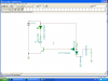
The sensors are here **broken link removed**

Looks the simplest without using photo or ir. Got most of the components already too. Detector cost about 70p per unit and signalling circuit cost about 50p per unit. Not too bad as to buy same from model shop about £17.00 !!!
 
here is an easier method

In TINA I simulated this very simple circuit. no transistors (depending on your sensors of coarse)
if you want the TINA file I can email it to you.
this circuit has been bugging me for severl days and BAM! came up with a very easy way to do it.
just remember the yellow and corresponding green is the block AFTER the red. That way the block where the train is is red with the yellow in the next block on.
one slight problem that just occured to me is that two green leds must be off. not a big deal I don't think.
 

Attachments

  • train blocks.PNG
    train blocks.PNG
    38.7 KB · Views: 240
Unfortunately I wouldn't be able to use the TINA layout as the demo only allows for about 9 components. Then it says it's too large a circuit for the demo version. I've tried one block but when green is on current through yellow/red is somewhat strange.

Reversing the switch and having red and yellow on seperate outputs onto one pole of the switch works, then green on the other pole of the switch, all with common ground.

**broken link removed**
 
the detector circuit is way out in left field.
its lke a shrine to the semi-conductor Gods.
a simple photo transistor either on both sides of track or one in between rail ties.
I think for all intentional purposes go with the orginal block LEDs signaling circuit and photo transistors in the track.
will get back to you as I have another idea on the signaling idea.
 
schematic and pcb layout

for one block
you mentioned 20 blocks
all on same board or separate boards?
As I mentioned I can etch and drill a board for you . you just pay for shipping.
I layed out board similar to schematic for ease of assembly etc.
large traces if you draw with felt pen
rethink your train sensors. the link you posted to wway to complicated for what your doing.
just photo transistors will do the deed IMO
 

Attachments

  • trainblockpcb.PNG
    trainblockpcb.PNG
    35.6 KB · Views: 210
  • block schematic.PNG
    block schematic.PNG
    27.9 KB · Views: 271
Appreciate that MrDeb.

Still having a problem with the signalling circuit tho'. Just built a third one, checked old components on previous board and they're all fine.

When the base is touched the green led glows brighter. Is this due to radio interference, i.e. signal diodes being used? This happens on the breadboard too.

I've lowered the led resistors so should the other resistors be lowered in resistance too?

I'm wondering if the stripboard is too much copper near to each other, thus an etched board might fix it. For example, I've put a gap between the collector ond base, and the base and emitter on both transistors. When I touch the track between the collector and base of Q1 the green led glows when yellow led is on.

Currently got problems with red led, it's not knocking off the green, but sharing power, both lit dimly. Gonna give my brain a rest for a day, then check circuit again.
 
a simple photo transistor either on both sides of track or one in between rail ties.

Looked at the photo transistor but it's no good for night operation, also the room where the model is is semi dark already as it's only got a small window.
 
use photo across the track

put IR on one side and detector on other.
seen this numerous times.
easier than the link you posted.
don't know why TINA allows only 9 components?
try loading a simple sample circuit then building another circuit next to it.
I know you have to have additional TI components in same window.
I will try and breadboard the circuit but don't have a clue why yours doesn't work?
 
Yay, I just removed a couple of the unused tracks between Q1 pins and it works apart from having a faint glow in green led. Even with all three blocks switched to occupancy they all show red with my stripboard circuit having a faint green led glow.

Not sure what's causing it but it's fainter than it was so when I etch the this the tracks will be as far away as possible from each other. It was like my finger on the base was acting as an antennae!
 
how many blocks prer board do you want?
been playing with IR train sensor.
what voltage do you have on the transistor Q1 base?
did you use 1n4148 diodes?
I wish you could use TINA and probe all the voltage points.
how about LT Spice?
 
voltage readings in block one

first is all blocks closed
second is all blocks open (no train)
I think its your soldering or a slight short??
try TINA again but with a sample circuit loaded up first on same screen.
check your PM and I will send Tina file?
 

Attachments

  • all sw grded.PNG
    all sw grded.PNG
    42.1 KB · Views: 213
  • sws open.PNG
    sws open.PNG
    49.5 KB · Views: 242
lets try something to track problem down

take photo of bottom (trace side) of your boards
start assembling one board with one block( 3 blocks would be better but.
Start by JUST soldering the GREEN LED componets ONLY (R1 and Q1 D1,D2)
then short to ground D2 output.
GREEN should come on full brightness.
ADD the RED LED componets (R4, R5, D5)
switching on/off the detect (switch to ground) the red should go off and red come on FULL BRIGHTNESS
if either of these tests fail then you have a soldering or component problem.
Are your diodes in correctly?
are they 1n4148?
correct resistors as per schematic (the R1 R3 and R5 can be 500-600 ohms instead but all must be same value)
let me know what happens.
 

Attachments

  • dim green led.PNG
    dim green led.PNG
    79.9 KB · Views: 227
  • green test.PNG
    green test.PNG
    63.7 KB · Views: 215
Back to Basics
Ok, going back to the breadboard circuit, I have two that work, I'm not touching them as I know they work.

So I switch blk1, so blk1 = red and blk2 = yellow.
Now if I touch the tip of a pair of metal tweezers to the base of Q1 the green lights dimly. I am not shorting it and there are no soldering issues as it's on the breadboard.

This is similar to the stripboard circuit, when the base of Q1 is touched or, before taking neighbouring tracks off, the green led is lit dimly.

Why does the green led light dimly? This is back to my earlier question, is there RF interference or any other interference from other components that, when the tweezers become an aerial they amplify?

Checking for shorts
I've scraped down between each of the tracks on the stripboard with a stanley blade, even to the point of removing some of the board. The problem still persists. I've checked under a magnifying glass and can see the board between every track so no shorts.

Resistor Values
All resistors are 560R. LED brightness is as equal as it could be. Do the 22K resistors have to be changed now the led reisistors values have been lowered?

TINA
I uninstalled Tina 8 and put in Tina 7, from the link you sent. It allows more components but I cannot 'activate' the circuit to test what happens when switches are thrown as the green button for that function is not present.

Diodes
All are 1N4148 with black band/cathode as per datasheet. Mounted correct way round as you can see here **broken link removed**
 
Last edited:
GREEN BUTTON??
you click on the T&M (between analisis and tools
click on the DMM-VOLTS
then when you click on the probe icon n the DMM the LEDs light up.
click the probe icon agai, then mouse over a switch(little arrow pops up, click on and switch is throwen
then click probe and other LEDs light up.
YOU must have at least one TI ic in the screen a;ll connected (use a sample circuit)
PLAY with it, youll get the hanfg of it.
Are you grounding the connection for the switch? hopfully yes.
If you study the schematic you can follow the current path.
What is the base voltage on Q1 with switch open?
 
why is R3 a different value than R1 & R5??
do you have a ground as pic dosn't show a terminal for ground??
I have a hunch the solution to this is real simple?
 
Ok, got TINA working. Working from this image **broken link removed**

I'm now using 560R on each LED on the latest stripboard build and breadboard builds. I had used different values to get equal brightness from led's.

I've added SW2 off board from blk- to ground to replicate red on block ahead, so yellow led lights.

Also added 12v out from board to common led positive.

Detect currently goes to ground via switch. When this all works, the detect circuit will be on same circuit board with detector power from main track power bus. Signalling side of optoisolator replaces SW1.

Base voltage Q1
SW1 open: 800.27mV
SW1 closed: 419.27mV
 
do you have a ground as pic dosn't show a terminal for ground??

Yep, ground for green led is lower of the two connections on the top left block connector.

Ground for detect is via switch on breadboard to common ground.

Voltage is from common 12V on breadboard.
 
does it look like its working?
if you pm me with your email I will send you the TINA file with all 5 blocks
when it looks like it works then probe different points and compare with your strip board.
I am curious why the strip board does not work?
Got to be a loose or missing connection.
 
Yep, leds change on and off. correct ones on at correct time.

PM sent with my email address.

Thanks for bearing with this slooow learner ;)
 
Status
Not open for further replies.

Latest threads

Back
Top