Continue to Site

Welcome to our site!

Electro Tech is an online community (with over 170,000 members) who enjoy talking about and building electronic circuits, projects and gadgets. To participate you need to register. Registration is free. Click here to register now.

  • Welcome to our site! Electro Tech is an online community (with over 170,000 members) who enjoy talking about and building electronic circuits, projects and gadgets. To participate you need to register. Registration is free. Click here to register now.

24 v battery charger vai 12

Status
Not open for further replies.
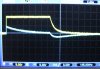
Just a side note seeing your oscilloscope curves: when you have a fast charge time and a slow discharge time, as it seems that you have, using TWO probes each near to two different charged capacitors, remember that those two probes create a circuit path between the two capacitors (probe tip 1, its internal resistance, its ground == ground of the second probe, internal resistance of the second probe, probe tip 2). In real life, that path won't be there. You can simulate the oscilloscope path on Spice adding the two 20MΩ resistances to see the curves that you got on the scope are... scope artefacts. Here, such an artefacts:
 

Attachments

  • Scope2Probes.jpg
    Scope2Probes.jpg
    1.2 MB · Views: 87
150W DC-DC Boost Converter 10-32V to 12-46V Step Up Charger Power Supply Module

s-l200.jpg

$7.68

Free shipping

**broken link removed**

well that was a really bad idea, applied power and hooked to the load and it let the smoke out in about 5 seconds, the transistors didn't have very good thermal insulation or adequate heatsink, looked pretty though.
 
Status
Not open for further replies.

Latest threads

New Articles From Microcontroller Tips

Back
Top