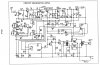
This schematic is fairly hard to follow, especially for a beginner.
Starting with R9, I believe that there should be a connection from the bottom side of R9 to that supply rail just below it. There is a dot there, and it should be there. R9 is simply a bias resistor to insure that Q4 has base current. In this case it makes sense that it connects directly to that rail, as mentioned. The line leading away from that junction, downwards, is for a circuit not directly related to R9.
As for R5, it also appears to require connection immediately below it as R9 did.
I realize now that I also neglected to give advice in my previous post on how to tune the AM/IF coil or the AM/OSC circuit. This is because I didn't study this thing closely enough. The circuit is perhaps somewhat complex for a beginner, but let's soldier on. The way I see it, if the FM/AM switch is in the FM position, Q1 and Q2 or biased ON and Q5 is OFF. So we can deduce that Q1 and Q2 only operate for FM. This means that the item labelled ANT is only the FM antenna, not the AM antenna. The AM antenna is the item labelled AM/COIL, but we'll get to that later.
Back to the FM circuit. Q1 is a tuned RF amplifier, set up to work around 88 to 108 MHz. Tuning the variable caps next to C7 would affect the sensitivity of the radio. C6 couples the amplified RF into a stage that operates as both an oscillator and a mixer. Its not clear to me what frequency it is meant to oscillate on since I can't tell from the circuit values alone. Those variable capacitors next to C12 and the 4mm 2.5T coil next to C12 on the other side form the high frequency tank circuit and determine the oscillator frequency. An oscillator like this is inherently operating non-linearly so it also will mix its own oscillation signal with whatever is coming in through C6 and so there will be some down-mixed result (the difference between the incoming on C6 and the oscillator frequency) coming through R6 at a much lower frequency and this lower frequency will find the transformer "FM/IF ORANGE" to be its favored path. So the low frequency IF signal will go through the transformer. I think that the transformer is already tuned but if there is a variable core visible inside it, you may have to tune this to peak the sensitivity (maximize the gain through this section). Q3 seems to be a simple amplifier to boost the IF signal, but it requires no tuning.
Q4 puzzles me. If it is an amplifier, then it is not clear how its output gets to the FM and AM detectors. The problem seems to be that the right side of R11 is connected to the positive supply rail. If it was not, then things might make more sense. Perhaps someone else can explain how this part works.
The FM detector appears to be some sort of ratio detector but I ahven't got time to analyze it thoroughly. Both the FM detector and the AM detector are fed signal. Fm detected output goes through R17 down the switch. From teh that point on the circuit is all just audio amplification.
For AM, the switch must be set to AM to turn on Q6 by providing a bias path through R13 to ground. The AM antenna is tuned with the two attached capacitors. These should be adjusted last and are usually varied for strongest output amplitude when receiving a weak station. The station frequency is mainly determined by tuning the two variable caps (and perhaps the AM/OSC PINK inductor/transformer) to the left of C18. You may also have to adjust the AM/IF YELLOW transformer too. I suspect that these AM adjustments will interact so you may have to go over them in sequence a few times before it is optimized. If tuning the antenna caps or the AM/IF YELLOW thing changes the frequency, then rotate them a bit at a time and each time go back to the AM/OSC PINK coil and two capacitors and reset the frequency with the capacitors. Then go back to the other variables again and try to get a stronger signal with a tiny bit more rotation.
In general, to get things right, start with "signal injection", the simple process of using a signal source (generator) to test each stage starting with the stage closest to the speaker and moving one by one backwards until you are injecting at the antenna. With this procedure, you should notice that as you go closer to the antenna, you need less signal level to inject. This is telling you that the amplifiers are amplifying. If you need more signal on the left of an amp, than on the right, then it is not working.
Obviously when you inject into Q8 or Q9 or Q7 or Q6, you should be injecting audio. In these cases, attach a DC blocked (use a large value blocking capacitor for audio, like 0.01 uF) audio signal into the base of each transistor. You should find that as you move from right to left, you need less and less signal to get the same output at the speaker. This decrease in input reflects the fact that you have amplification from Q7 and Q6.
You do the same sort of thing with Q4, 3, 2 and 1 except that you have to use an FM modulated carrier, coupled with a smaller cap (say 1000 pF) instead of audio. Inject in to the base of Q4 or Q3, or into the emitter of Q2 or Q1 and note that the amount of injection needed should decrease as you go left to right. If it does not, then that stage may not be working correctly. You also have to change the frequency as you go to the left. Q4 and Q3 operate at the IF frequency. Q2 and Q1 at the RF frequency.
Give it a try.
")
