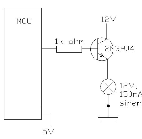
I corrected the diagram. Is it OK now?
15mA is too much for PIC MCU, or it is absolute maximum. I need other NPN then, the one that has higher base/collector current ration, at least 3 times higher - can you help to fing some?
That's not the best approach. You need to understand how bipolar junction transistors work, then you'll understand that the above isn't what you need.
As I understand it -- and the gurus will correct me, I don't doubt -- BJTs can either be "off", operate as amplifiers, or operate "fully on". To act as a switch, that is, maximizing current through the driven device, and minimizing the voltage drop across the collector/emitter and thus reducing heat, you need to run the BJT in the "fully on" or "saturation" mode. Essentially saturation occurs when you can't get any more current into (out of) the collector with additional base current.
To ensure a BJT is in saturation the
rule of thumb is to force 1/10th the desired collector current into the base by selecting the base resistor value. As mentioned there's usu. a voltage given in the datasheet as to when the transistor just enters saturation. But you want to push it well beyond that point to ensure it doesn't come out of saturation (e.g., your wall or battery voltage sags and drops Vcc, or resistor is a little out of spec or tolerances on the BJT, or I donno what)
You may know about the key relationships. Ie (emitter current) = the sum of Ic and Ib. Also, Vbe = 0.7V for any silicon BJT. With those two facts, plus ohm's law, and kirchoff's voltage law you can figure out everything else as you may have surmised.
The 270Ω resistor was figured out using both of these, etc. V = IR, Vcc - Vbe / Ib = R, 5V - 0.7V / 15mA = 286Ω 270 would add a little extra current, no problem.
Anyway hope that helps.
Michael