Does hFE tells how many times is the collector-emitter current greater that base-emitter?
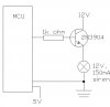
I need to control 12V, 150mA siren connected to the PIC MCU putput and I thought I would use 2N2904 NPN and connect like diagram shows. I am not sure if I choosed the right transistor.
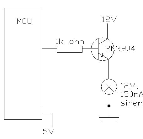
I need to control 12V, 150mA siren connected to the PIC MCU putput and I thought I would use 2N2904 NPN and connect like diagram shows. I am not sure if I choosed the right transistor.