Electro Tech is an online community (with over 170,000 members) who enjoy talking about and building electronic circuits, projects and gadgets. To participate you need to register. Registration is free. Click here to register now.
Welcome to our site! Electro Tech is an online community (with over 170,000 members) who enjoy talking about and building electronic circuits, projects and gadgets. To participate you need to register. Registration is free. Click here to register now.
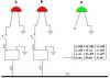
Have 2 LED's they each have there own switch for on/off. I wish to add a 3rd LED but I only want the 3rd to light up when the 1st two are both on. How do I do this?
I like your idea. I guess some back ground would help. The 1st dawing is for my general goal.
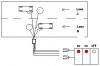
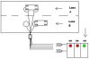
Have multiple inductive loops in roadway with unmarked leads coming to side of road. Using loop detectors and combining them to make this work. Each loop detector will flash an LED when a car drives over an individual loop. My problem is that I have a lot of loops in road. Need to see which are lead or trail loops. Loops are 6' diameter and 16' leading edge to leading edge. When a car sets on 2 loops at same time within same lane I want a 3rd LED to light up which in turn tells me I have the correct 2 loops leads and correct lane.
If a car in lane A sets on a lead loop and car in lane B sets on trail loop then the 3rd LED will not light up.
This is my concept and I think it will work just need help on the electronics part of it.
Forgot to mention that my switch in the first drawing represents my loop detectors which switch on/off the individual LED's.
Was hoping to only splice into the wiring of the LED's on the loop detectors to somehow make the 3rd one light up. Did that statement make sense I hope?
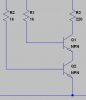
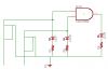
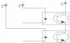
If you connect the input of opto-couplers in series with each red LED then connect the outputs in series and to the green LED the green LED will only come on when both red LED's are on.
I'm not sure if 74ALS08 could provide sufficient current for the 3rd LED in
such configuration even to get it enough to turn on. TTLs usually can
sink more current so NAND gate would be better (the ALS08 gate can
sink only ca 8mA).
I'm not sure if 74ALS08 could provide sufficient current for the 3rd LED in
such configuration even to get it enough to turn on. TTLs usually can
sink more current so NAND gate would be better (the ALS08 gate can
sink only ca 8mA).
you are right i should have drawn it to sink the current ..but what the heck it was the idea of using an AND gate that i was trying to get across.
the ALS08 was just the first one i came across.. a 7408 would work..
The and function is taken care of the opto coupler outputs being in series, plus using opto couplers does not require using an additional 5V power source.
See attached schematic
This site uses cookies to help personalise content, tailor your experience and to keep you logged in if you register.
By continuing to use this site, you are consenting to our use of cookies.