Continue to Site

Welcome to our site!

Electro Tech is an online community (with over 170,000 members) who enjoy talking about and building electronic circuits, projects and gadgets. To participate you need to register. Registration is free. Click here to register now.

  • Welcome to our site! Electro Tech is an online community (with over 170,000 members) who enjoy talking about and building electronic circuits, projects and gadgets. To participate you need to register. Registration is free. Click here to register now.

1973 Garage door opener( dip switch type) Lost remote

Status
Not open for further replies.
I wouldn't bother. I bought **broken link removed**, and they work great. I now have one of the receivers hooked up to my motorized gate, two different garage door operators, and a light. I have five of the remotes all strapped to one code. With the receiver connected to a full size dipole antenna (outside my metal building), the range is about 300ft.
 
what model, you may be able to find the frequency and other info like how many dip switches to uses etc...
 
OK, it's a Sears Receiver # 139.654020 with 9 pin dip
 

Attachments

  • WP_20150101_004.jpg
    WP_20150101_004.jpg
    1.2 MB · Views: 1,016
Last edited:
I think I can see the parts I need from this old black and white. but I still can't locate the frequency.
 

Attachments

  • WP_20150102_005.jpg
    WP_20150102_005.jpg
    1.6 MB · Views: 485
A Sears door opener is very likely made by Chamberlain (Liftmaster). There is a lot of information on the web about those openers. It if meets current safety standards, then you can contact Chamberlain. If not, then the web is your best resource. An elderly neighbor had one such older unit. Chamberlain refused to provide any information whatsoever. I was able to help her with a new transmitter and receiver that I spliced into her operator, so she could avoid the cost of a whole new system.

Some Chamberlain systems have selectable frequency.

John
 
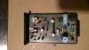
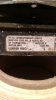
There is coil on receiver board. So most likely frequency is set by LC circuit and transmitter probably has same coil and capacitor, several transistors and IC. To determine frequency you need to measure inductance of coil and look what capacitance has capacitor, then calculate frequency. Or build transmitter using this coil and cap and measure it's frequency. You likely don't have frequency meter or very accurate LC meter to do so.
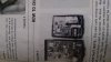
And this is not only problem. Main frequency is modulated by IC. Your receiver has 125c7 rx(rx means receiver) and transmitter probably had 125c7 tx. 125c7 tx modulates transmitter frequency and sends code (which is set by switches) to receiver, where 125c7 rx decodes and checks the code. So you need to find 125c7 tx or emulate it by using microcontroller(and you need how to program them), in this case you need working transmitter to reverse engineere protocol, this is not simple task by itself, or documentation where communication protocol of these IC's is described, but i couldn't find any datasheet of this IC after short googling.

It's easier and cheaper to buy new transmitter and receiver, than to try make transmitter for this
 
...
It's easier and cheaper to buy new transmitter and receiver, than to try make transmitter for this
I already gave the TS the $4 solution above...
 
You will find the case to put the transmitter in is more expensive than everything else and harder to come by. In the anecdote I related, bought a new transmitter in a small keyfob and receiver for not that much more. Then all I had to do was circuit trace the operator to find where to splice the receiver into the system.

John
 
This is what I've rigged up to operate my door for now....lol...pretty cool huh ?

This isn't very good idea. All rc cars i had had small control range, and they haven't any protection, in your current receiver you need to send same code as set by switches in receiver. Anyone with same rc car controller can open your door. Controllers are same for most cheap rc cars and they work on same 27Mhz frequency, even neighbours kid can open your door playing with his rc car.


This is only receiver and transmitter, you can transfer any data with them. But you can't connect this receiver to transistor or relay, you need microcontroller for transmitter to send code, and microcontroller for receiver to check code and control transistor/relay
 
You need not only to buy microcontrollers, but also write program for them. Microcontroller is like small computer, you need to program it to make it do what you need. You can use arduino, it's simple and has lot of examples.
 

Those do not have the encoder chip on the transmitter or the decoder chip on the receiver, and are almost worthless for your project (unless you really like to fiddle)! Use the ones I linked to.
There is likely to be less interference on the 315MHz ISM band than on the 433MHz ISM band.
 
Done , Thanks MikeML and nyaknyan and jpanhalt. I ordered 2 of the 315MHz. Do they have to be programmed ? I've seen examples, seems like basic computer programming language. So I'm basically telling the receiver that when it receives a signal to apply a small voltage across the push button actuator wires thus opening the door.
 
Done , Thanks MikeML and nyaknyan and jpanhalt. I ordered 2 of the 315MHz. Do they have to be programmed ? I've seen examples, seems like basic computer programming language. So I'm basically telling the receiver that when it receives a signal to apply a small voltage across the push button actuator wires thus opening the door.

The only programming is soldering some jumpers across the address pins of the encoders in transmitters, and placing the same pattern of jumpers on the matching decoder on the receiver. I think there are about 9 address pins. Each pin can be left open, grounded, or tied to Vcc, so this gives 9^3 addresses. They arrive unstrapped, so that the transmitters talk to the receiver, but it would be on the default code. You can think of these solder jumpers like the dip-switch in your old system, but it takes a soldering iron to program them.

The receiver produces a CMOS logic output when the corresponding button on the transmitter is pushed. It can drive a LED indicator unbuffered. When I interfaced my receiver to the existing garage door operators, I put a small 5V relay and a NPN transistor between the receiver and the existing garage door wall-mounted push button circuit.
 
Ok, so after a long interruption I'm back to my project. I have the parts and I have worked out the values for R1 and the Transistor but I'm confused on where I ground the emitter.I have 7 pins, left to right....VT ,D, C, B, A, 5v+, 5v- . I have a 5v DC power supply connected to the 2 pins on the right. I have the base of the transistor connected to
R1 and output pin C. I have the collector connected to the diode protected coil of the relay. My question is, do I connect the other side of the coil to the high output pin (VT)
and where do I ground the emitter ?
this schematic shows an extra diode and the VT pin isn't even used:banghead:.
 

Attachments

  • Screenshot (48).png
    Screenshot (48).png
    248.8 KB · Views: 317
The -5V is misnamed. It should really be named 0V or Gnd, the return terminal to the 5V power supply. That is where to connect the emitter of the NPN transistor. The extra diode between the output pin and the base of the NPN isn't really needed, but won't hurt anything.
The Vt out a test point, and you don't connect anything to it...

If you use a 5V relay, you can get by without a 12V supply. If you do use a 12V supply, then obviously its 0V side must also connect to the rightmost pin on the receiver.
 
Status
Not open for further replies.

Latest threads

New Articles From Microcontroller Tips

Back
Top