october71
New Member
Hi all,
I'm fairly new here, though I have been reading posts for a while, I finally decided to register and post.
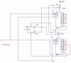
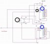
I'm trying to make a 16-step sequencer using the 10-step LED sequencer schematic that's out there which uses the 4017 decade counter IC. I've tried to cascade two 4017s together but the only things I can get it to do are:
1. one 4017 counts ones, the second one counts 10s
2. one 4017 advances one, then the other 4017 advances one (but has both steps on at the same time, which I don't want)
3. both 4017s simultaneously counting ones.
If I can get this thing to sequentially count to 20, I can shorten the steps to 16, which is *exactly* what I want. Help, please!!
Thanks in advance,
I'm fairly new here, though I have been reading posts for a while, I finally decided to register and post.
I'm trying to make a 16-step sequencer using the 10-step LED sequencer schematic that's out there which uses the 4017 decade counter IC. I've tried to cascade two 4017s together but the only things I can get it to do are:
1. one 4017 counts ones, the second one counts 10s
2. one 4017 advances one, then the other 4017 advances one (but has both steps on at the same time, which I don't want)
3. both 4017s simultaneously counting ones.
If I can get this thing to sequentially count to 20, I can shorten the steps to 16, which is *exactly* what I want. Help, please!!
Thanks in advance,
") Anyone else?
Anyone else?