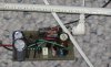
Here's something quirky, I had the circuit running again and I noticed the .2 ohm resistor getting warm and started checking voltages and found it was generating 70+ volts, 33 across the load and 40 across the current limiter, but with the current limiter working good, the lights survived, and if I turned the supply down 14 to about 5 or 6, the voltage remained high until the supply got low, then the output went to 36 and stayed there, even when I turned the supply up to 20, and if I disconnected the power and then reapplied it, the voltage went back up to 70+. I also notice the frequency was around 2 - 3 KHz when the voltage was high and 109 KHz when the voltage was 33.
Any one have any ideas on how to stabilize this??
Kinarfi
") Sometimes you get lucky.
Sometimes you get lucky.")