Electro Tech is an online community (with over 170,000 members) who enjoy talking about and building electronic circuits, projects and gadgets. To participate you need to register. Registration is free. Click here to register now.
Welcome to our site! Electro Tech is an online community (with over 170,000 members) who enjoy talking about and building electronic circuits, projects and gadgets. To participate you need to register. Registration is free. Click here to register now.
not real good, I would limit the current with an LM317 set up as a current limiter, I've been trying the same thing, but the gate capacitance causes a huge change of frequency so I need to put a buffer between the 555 and the FET. I looked at R Black did, but those are buck set ups and I need boost, something simple like that is what I'm looking for.
Thanks,
Kinarfi
Sure we can, 2 xistors for an oscillator, and one for an amp and one FET to power the inductor and a cap. Now if I just knew the correct configuration to hook them up in.
I have a low voltage version in projects under no frills boost. There are some improvements there. But have a look at this one. I think it's pushing things with 33Uh. The 555 is not real fast. So maybe two of the inductors with an 85 Khz oscillator would be better. See what you think.
Sure we can, 2 xistors for an oscillator, and one for an amp and one FET to power the inductor and a cap. Now if I just knew the correct configuration to hook them up in.
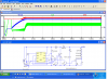
Here's one that looks good on spice, but when I built it, the frequency dropped from around 400k Hz to under 300k Hz so I need a buffer between the osc and the FET. Maybe a totem pole will work. Any one have any suggestions?
Kinarfi
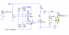
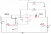
The chip implementation is probably best, but here is one that might do it if you want parts.
Needs a good FET (low Rds on and low gate charge) and a good cap (low ESR and high temp) foe C2. Let me know if you decide to build it.
Do you have a big inductor?
PS. I used zeners for the simulation cause I didn't have your fancy 10 volt LEDs.
Thanks, that looks pretty good, I will build it! I have several inductors salvaged from server power supplies, in big, do you mean physically or higher u henries? Mine are large. I made some changes to what you posted to devices I have in spice, specifically the pot and the FET and the load diodes, they all came with my recent down load and installation of LTspiceIV.exe and LtSpiceIV_Plus_12_2009.exe on my older laptop because my Toshiba crashed again and is headed back to the factory. The oscillator 4 fet.asc is the one mentioned earlier, runs at about 400khz until I tie it to an IRF2805, may work with that some more too.
Thanks for the current boost.asc,
I'm off to build it.
Kinarfi
If you are driving 50W load power from 14V input, peak switch current (and inductor current) is probably going to be over 5A. Make sure the inductor can handle it without saturating.
I believe the Simple Switcher product family has some 5A rated boost converters which would make this more simple. You're going to have a hell of a time building discrete drivers that can slam the gate up and down fast enough to minimize switching losses. Not to forget, if you build it from discrete components it won't have any over current protection which is death for a boost switcher which pulls huge peak currents at startup.
The op amps can't run at that speed and can't supply enough current to switch the FET fast enough.
.......................................
Here is a calculator where you can plug in values to see what frequency and inductor size you need. https://www.daycounter.com/Calculators/Switching-Converter-Calculator2.phtml
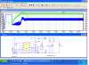
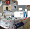
I built it and it ran, I did make a few pieces of trash though, the first 1.5 Ω resistor went to 150, then ∞ and so did the first 39Ω resistor allowing out put voltage to go to +90 volt and the schottky diode was only rated for 45, after I figured out what was dead and what was good, I replace the diode with an ultra fast 8 amp 600 volt diode, the 1.5Ω resistor with a 3 watt and put in another 39Ω resistor and turned it on and I could adjust the current until the second 39 failed in maybe 30 seconds.
I was monitoring everything with 2 fluke 97s, volts and current, and a PC oscilloscope and after the 39Ω resistor failed, I turned the power supply off and went to unsolder the resistor and heard the nasty loud pop of the charged cap discharging into the tip of my soldering iron, the music I was listening to quit also and then I noticed my computer oscilloscope had also quit because my computer was off, and I haven't been able to turn it back on yet, it may be the most expensive piece of trash I created and maybe my DSO2150 oscilloscope died too. Still have more testing to do and trying to see what went.
But the circuit worked.
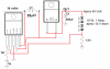
Attached it the circuit I built and some photos of it showing the inductor I used. I cut some of the non related parts out of the photo.
Thanks for the help,
Kinarfi
What a bummer!
I hope it all comes back to life.
If you keep going, add the other inductor for a total of 66 Uh. and make R6 .1 ohm 5 watt so the current limit will work.
I'm trying to think what you could use for a load.
What a bummer!
I hope it all comes back to life.
If you keep going, add the other inductor for a total of 66 Uh. and make R6 .1 ohm 5 watt so the current limit will work. I'm trying to think what you could use for a load.
I already made my own wire wound adjustable resistor and it works pretty well, not sure what the wattage would be, but I know it's a very high wattage resistor. I did find that the current varied, I guess I still have lots to learn about the 555, I'll do what you said and get back to you.
yea, it's about 30 to 50 yards of .032 stainless safety wire, but I'm not safety tying much any more, so it's pretty good use for it and it won't damage it.
This site uses cookies to help personalise content, tailor your experience and to keep you logged in if you register.
By continuing to use this site, you are consenting to our use of cookies.

")